
Page 1400 - Softbound_Edition_19_en
P. 1400
Line mount bodies Accessories
Line mount bodies
GENERAL SPECIFICATIONS SCREW-IN CARTRIDGES INSTALLED Threaded ports sandwich body
Description Line mount body According to the type the following screw-in cartridges can be installed ®
Mounting 2 location holes in the line mount bodies: • p max = 350 bar NG3-Mini
2 tapped holes
Connection Threated connections Type Data sheet no.
Mounting position see valve data sheet DESCRIPTION APPLICATION
Surface protection zinc-nickel coated M16x1,5
MD.PM16 2.2-508 Sandwich bodies NG3-Mini acc. to Wandfluh Threaded ports sandwich bodies in stacking
MDBPM16 2.3-602 standard with ports G1/8" for external conn- systems to connect gauges, sensors or control
HYDRAULC SPECIFICATIONS MDIPM16 2.3-603 ection to A and B or P and T lines. Sandwich elements.
Peak pressure p max = 400 bar MDPPM16 2.3-605 bodies with one external connection (A, B, P,
MGPPM16 2.3-607 T) will have the second port plugged with plug
MGBPM16 2.3-608 G1/8" (article 238.1405). The sandwich bodies
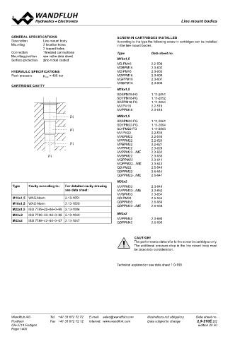
CARTRIDGE CAVITY are zinc coated and will be supplied inclusive
M18x1,5 5 O-rings ID 4,50x1,50 (article 160.2045).
M18x1,5 The connections T and To are not connected
SDSPM18-FG 1.11-2051
SDYPM18-FG 1.11-2052 together.
SDZPM18-FG 1.11-2054
MV.PM18 2.2-510 TYPE CODE
MVPPM18 2.3-610
(3) M22x1,5 PG S A03 #
SDSPM22-FG 1.11-2061 Sandwich threaded body
SDYPM22-FG 1.11-2064
(2) SLYPM22-FG 1.11-2066 Sandwich construction
MV.PM22 2.2-530
MVEPM22 2.2-536 Mounting interface acc. to Wandfluh standard, NG3-Mini
MPPPM22 2.2-625
(1) MPBPM22 2.2-627 Type list / Function
MVPPM22 2.3-629 in A A in P P
MVPPM22-../ME 2.3-632 in B B in T T
(1) MVBPM22 2.3-635 in A and B AB in P and T PT
MQPPM22 2.3-641
MQPPM22-../ME 2.3-643 Design-Index (Subject to change)
QD.PM22 2.5-540
QDPPM22 2.6-644
QDPPM22-../ME 2.6-647 TYPES DIMENSIONS ∅ 4,2
M33x2 ∅ 4,2
Type Cavity according to: For detailed cavity drawing MVPPM33 2.3-649 PGSA03-A
see data sheet: MVPPM33-../ME 2.3-652 (article 203.0501) G1/8" G1/8"
MVBPM33 2.3-654 P T B
M16x1,5 WAG-Norm 2.13-1051 QD.PM33 2.5-555 A P T B A 30
M18x1,5 WAG-Norm 2.13-1020 QDPPM33 2.6-666 30
QDPPM33-../ME 2.6-668 PGSA03-B 15
M22x1,5 ISO 7789–22–04–0–98 2.13-1004 (article 203.0502) 15
M33x2 ISO 7789–33–04–0–98 2.13-1040 M42x2
M42x2 ISO 7789–42–04–0–07 2.13-1047 MVPPM42 2.3-690 A P T B A P T B PGSA03-A, B, AB 20
QDPPM42
2.6-695
20
PGSA03-AB 10 10
(article 203.0500)
CAUTION! P
The performance data refer to the screw-in cartridges only. A P T B A P T B P
The additional pressure drop in the line mount body must A 30 B A B 11 21
be taken into consideration. PGSA03-P 30 A A B 11 21 B
(article 203.0504) T 15 To T To
15
A P T B
Technical explanation see data sheet 1.0-100 A P T B 30
30
PGSA03-T 60
(article 203.0505) 60
PGSA03-P, T, PT
A P T B
A P T B P
PGSA03-PT P P A B P
(article 203.0503) A B
T T To 5,5
A P T B T T 5,5 To 5,5
A P T B 5,5
Wandfluh AG Tel. +41 33 672 72 72 E-mail: sales@wandfluh.com Illustrations not obligatory Data sheet no. Wandfluh AG Tel. +41 33 672 72 72 E-mail: sales@wandfluh.com Illustrations not obligatory Data sheet no.
Postfach Fax +41 33 672 72 12 Internet: www.wandfluh.com Data subject to change 2.9-210E 2/2 Postfach Fax +41 33 672 72 12 Internet: www.wandfluh.com Data subject to change 2.10-10E 1/1
CH-3714 Frutigen Edition 20 30 CH-3714 Frutigen Edition 13 25
Page 1400