Page 1398 - Softbound_Edition_19_en
P. 1398

Line mount bodies                                                                                                            Line mount bodies
                                                                                           Line mount bodies

                                                                                                                                   Line mount body                               M16x1,5          M33x2
       GENERAL SPECIFICATIONS                              SCREW-IN CARTRIDGES INSTALLED
       Description    Line mount body                      According to the type the following screw-in cartridges can be installed   •  for 3-way-valves                        M18x1,5          M42x2
       Mounting       2 location holes                     in the line mount bodies:                                                 in screw-in cartridge construction
                      2 tapped holes                                                                                               • p     =  400 bar                            M22x1,5
       Connection     Threated connections                 Type             Data sheet no.                                            max
       Mounting position   see valve data sheet
       Surface protection   zinc coated                    M18x1,5
                                                           SDSPM18-BA/AB    1.11-2050                                              TYPES                              TYPE CODE
                                                           SDYPM18-BA/AB    1.11-2052
       HYDRAULC SPECIFICATIONS                             SDZPM18-BA/AB    1.11-2054                                                                                                                                KG          -  F04  #
       Peak pressure   p max  = 400 bar                    SVSPM18-BC/CB    1.11-2080                                              F04                                Line mount body made of steel
                                                           DN.PM18          2.4-510                                                                                   Port size           G 1/4“  G14   G 3/8“   G38   G 1/2“ G12
                                                           DR.PM18          2.4-610
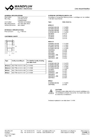
       CARTRIDGE CAVITY                                    QA.PM18          2.5-510                                                                                                       G 3/4“  G34   G 1 1/4“  G114
          M18x1,5                                          D.PPM18          2.6-510                                                                                   Cavity thread diameter   M16x1,5   16   G 1/4“
                                                                                                                                                                                          M18x1,5    18     G 3/8“
                                                           M22x1,5                                                                                                                        M22x1,5    22     G 3/8“ und G 1/2“
                                                           SDSPM22-BA/AB    1.11-2060                                                                                                     M33x2      33     G 3/4“
                                                           SDYPM22-BA/AB    1.11-2064                                                                                                     M42x2      42     G 1 1/4“
                   (2)
                                                           SVSPM22-BC/CB    1.11-2082                                                                                 Variations          F04
                                                           SVYPM22-BC/CB    1.11-2084                                                                                 Design index (subject to change)
                                                           QRSPM22          2.5-530
                    (1)                                    QZ.PM22          2.5-535                                                DIMENSIONS F04
                                                           DNPPM22          2.6-531
            (1)                                            DNPPM22-../ME    2.6-541                                                       P  P
                                                           QNPPM22          2.6-631                                                      E  E
                                                           QNPPM22-../ME    2.6-633                                                          2  2                          N  N
       Type    Cavity according to:   For detailed cavity drawing   M33x2
                                 see data sheet:                                                                                                                                 M6  M6
                                                           SVSPM33-BC/CB    1.11-2076
       M18x1,5  ISO 7789–18–01–0–98 2.13-1002              SVSPM33-BA/AB    1.11-2076
                                                           SVYPM33-BC/CB    1.11-2085                                                                         I  I
       M22x1,5  ISO 7789–22–01–0–98 2.13-1008              SVYPM33-BA/AB    1.11-2085                                                                       1  1    L   L          A   A
       M33x2   ISO 7789–33–01–0–98 2.13-1005               QZ.PM33          2.5-550
                                                           DNPPM33          2.6-551                                              D  D
       M42x2   ISO 7789–42–01–0–07 2.13-1050               DNPPM33-../ME    2.6-561                                                                           H  H  K   K
                                                           QNPPM33          2.6-651
                                                           QNPPM33-../ME    2.6-659
                                                           QSPPM33          2.6-661                                                      3  3      M   M                   B  B
                                                                                                                                       F  F    Ø6,5  Ø6,5
                                                           M42x2                                                                         G  G
                                                           SVSPM42-BA/AB    1.11-2091                                                       O  O
                                                           QNPPM42          2.6-690                                                           C  C

                                                                                                                                   TYPE F04
                                                                    CAUTION!
                                                                    The performance data refer to the screw-in cartridges only.       Ordering   Size         Ports                              Dimensions (in mm)                 Weight
                                                                    The additional pressure drop in the line mount body must           code
                                                                    be taken into consideration.                                                       1     2     3    M    A   B   C  D   E    F  G   H    I  K   L   N   O   P
                                                                                                                                    KGG1416-F04  M16x1,5  G 1/4“  G1/4“  G1/4“  G1/4“  60  40  60  30  20.3  13  28  8  44  15  30  30  44  38  0.98
                                                                                                                                    KGG3818-F04  M18x1,5  G 3/8“  G3/8“  G3/8“  G1/4“  70  30  80  35  32.8 17.3 32.5  18  44  20  30  22  60.5  48  1.10
                                                           Technical explanation see data sheet 1.0-100                             KGG3822-F04  M22x1,5  G 3/8“  G3/8“  G3/8“  G1/4“  80  45  100  40  44  22.5  55  11  58  25  30  32  77  25  2.45
                                                                                                                                    KGG1222-F04  M22x1,5  G 1/2“  G1/2“  G1/2“  G1/4“  80  45  100  40  44  22.5  55  11  58  25  30  32  77  25  2.45
                                                                                                                                    KGG3433-F04  M33x2  G 3/4“  G3/4“  G3/4“  G1/4“  100  50  110  50  58.5 30.5  70  11  80  27.5  45  34  89.5  35  3.40
                                                                                                                                    KGG11442-F04  M42x2  G 1 1/4“ G 1 1/4“ G 1 1/4“ G1/4“  120  60  130  60  66.5 33.4  72  15  88  32.5  55  44  100  25  5.40


       Wandfluh AG        Tel.  +41 33 672 72 72   E-mail:  sales@wandfluh.com   Illustrations not obligatory   Data sheet no.     Wandfluh AG         Tel.  +41 33 672 72 72   E-mail:  sales@wandfluh.com   Illustrations not obligatory   Data sheet no.
       Postfach           Fax  +41 33 672 72 12   Internet:  www.wandfluh.com   Data subject to change   2.9-205E 2/2              Postfach            Fax  +41 33 672 72 12   Internet:  www.wandfluh.com   Data subject to change   2.9-210E 1/2
       CH-3714 Frutigen                                                                            Edition 17 01                   CH-3714 Frutigen                                                                             Edition 20 30
       Page 1398
   1393   1394   1395   1396   1397   1398   1399   1400   1401   1402   1403