
Page 1397 - Softbound_Edition_19_en
P. 1397
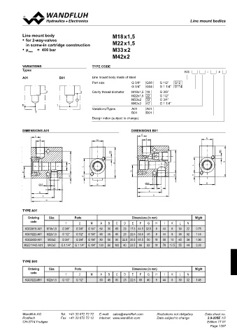
Line mount bodies
 Line mount bodies                                                                               Line mount bodies

            Line mount body                               M18x1,5
 GeneraL sPeCifiCations  sCrew-in CartriDGes instaLLeD
 Description   Line mount body  According to the type the following screw-in cartridges can be installed   •  for 2-way-valves   M22x1,5
 Mounting   2 location holes  in the line mount bodies:  in screw-in cartridge construction
    2 tapped holes  • p    =  400 bar                     M33x2
 Connection   Threated connections  Type   Data sheet no.  max
 Mounting position   see valve data sheet                 M42x2
 Surface protection   zinc coated  M18x1,5
 BV.PM18   2.1-510  VARIATIONS                 TYPE CODE
 BS.PM18   2.1-520  Types
 HYDraULC sPeCifiCations  BS.PM18-Z36   2.1-522                                               KG          -    #
 Peak pressure   p max  = 400 bar  BVPPM18   2.3-510  A01   B01  Line mount body made of steel
 BDPPM18   2.3-520
 CartriDGe CavitY                              Port size           G 3/8“   G38   G 1/2“   G12
                                                                   G 3/4“   G34   G 1 1/4“  G114
 M22x1,5                                       Cavity thread diameter   M18x1,5  18   G 3/8“
 BV.PM22   2.1-530                                                 M22x1,5  22    G 1/2“
 BVTPM22   2.1-532                                                 M33x2   33    G 3/4“
 BVEPM22   2.1-536                                                 M42x2   42    G 1 1/4“
 (2)  BA.PM22   2.1-540                        Variations/Types    A01     A01
 BK.PM22   2.1-542                                                 B01     B01
 BS.PM22-Z36   2.1-543                         Design index (subject to change)
 (1)  BVPPM22   2.3-529
 BVPPM22-../ME   2.3-537
 BNIPM22   2.3-533
 (1)  BVBPM22   2.3-536  DIMENSIONS A01                            DIMENSIONS B01
 BDPPM22   2.3-539  E                                                   E
 BDPPM22-../ME   2.3-561  2                       N                       2                              N
 BDIPM22   2.3-548
 type  Cavity according to:   for detailed cavity drawing   BDIPM22-../ME   2.3-562
 see data sheet:  BDBPM22   2.3-547
                                                         M6                                                     M6
 M18x1,5  ISO 7789–18–02–0–98 2.13-1001  M33x2
 M22x1,5  ISO 7789–22–02–0–98 2.13-1003  BV.PM33   2.1-550  I  A                         I                        A
 M33x2  ISO 7789–33–02–0–98 2.13-1041  BVPPM33   2.3-551  1  L                                    L
 BVPPM33-../ME   2.3-553                                           D
 M42x2  ISO 7789–42–02–0–07 2.13-1048  D                                                 H        K
 M42x2                              H      K
 BVPPM42   2.3-590  Ø6,5                          B                       Ø6,5                           B
                                                                          G       1
                            M
                                                                            F
                     G
                                                                              C
                      F
 CaUtion!               C
 The performance data refer to the screw-in cartridges only.
 The additional pressure drop in the line mount body must
 be taken into consideration.  TYPE A01
               Ordering   Size         Ports                       Dimensions (in mm)              Wight
                code
 Technical explanation see data sheet 1.0-100   1  2  M  A  B  C  D  E  F  G   H   I   K   L   N
              KGG3818-A01  M18x1,5  G 3/8“  G 3/8“  G 1/4“  60  30  65  23  17.3 44.5 32.5  8  44  8  30  22  0.75
              KGG1222-A01  M22x1,5  G 1/2“  G 1/2“  G 1/4“  60  45  80  23  22.5 53.5  40  8  44  8  30  32  1.45
              KGG3433-A01  M33x2  G 3/4“  G 3/4“  G 1/4“  80  50  80  32.5 30.5 61.5  50  11  58  10  45  34  1.90
             KGG11442-A01  M42x2  G 1 1/4“  G 1 1/4“  G 1/4“  100  60  100  40  33.5  80  62  11  78  12.5  55  44  3.20


            TYPE B01

               Ordering   Size         Ports                       Dimensions (in mm)              Wight
                code              1      2     M   A   B   C   D   E   F   G   H   I   K   L   N
              KGG1222-B01  M22x1,5  G 1/2“  G 1/2“  60  45  80  23  22.5  60  40  8  44  8  30  32  1.45


 Wandfluh AG   Tel.  +41 33 672 72 72   E-mail:  sales@wandfluh.com   Illustrations not obligatory   Data sheet no.  Wandfluh AG   Tel.  +41 33 672 72 72   E-mail:  sales@wandfluh.com   Illustrations not obligatory   Data sheet no.
 Postfach   Fax  +41 33 672 72 12   Internet:  www.wandfluh.com   Data subject to change   2.9-200E 2/2  Postfach   Fax  +41 33 672 72 12   Internet:  www.wandfluh.com   Data subject to change   2.9-205E 1/2
 CH-3714 Frutigen     Edition 14 09  CH-3714 Frutigen                                                    Edition 17 01
                                                                                                           Page 1397