Page 1306 - Softbound_Edition_19_en
P. 1306

Proportional flow control valves                                                                                             Proportional flow control valves
                                                                               Proportional flow control valve

       ELECTRICAL SPECIFICATIONS                            HYDRAULIC SPECIFICATIONS                                               DIMENSIONS / SECTIONAL DRAWINGS
       Construction        Proportional solenoid, wet pin push type,   Fluid    Mineral oil, other fluid on request                                                                                      Cavity drawing acc. to
                           pressure tight                   Contamination efficiency   ISO 4406:1999, class 18/16/13                                                                                     ISO 7789–42–04–0–07
       Standard nominal voltage  U = 12 VDC  U = 24 VDC                         (Required filtration grade β 6…10 ≥ 75)                                                                                          M42x2
                                                                                see data sheet 1.0-50/2
       Limiting current     I G  = 2255 mA  I  = 1105 mA    Viscosity range     12 mm /s…320 mm /s                                               10
                                                                                              2
                                                                                     2
                                           G
       Relative duty factor   100 % ED / DF (see data sheet 1.1- 430)  Fluid temperature   -20…+70 °C                                69   20                         s41   M42x2  3 (A)  2 (T)
       Protection class    Connection version               Peak pressure       p max  = 350 bar                                        15
                                                                                   = 160 l/min
       acc. to  EN 60 529   D: IP 65                        Nominal volume flow rates  Q N   = 200 l/min (1 → 2)
                                                            Max. volume flow
                                                                                Q
                           J:  IP66                         Min. volume flow     max   = 0,5 l/min                                                                                             1 (P)                         (3)
                           G: IP 67 and 69K                 Hysteresis          Q min
                                                                                ≤ 6 % ٭
       For further electrical specifications see data sheet  1.1-191            ٭ at optimal dither signal                           32
                                                                                                                                                                                                                             (2)
                                                                                                                                               17                          50 80 60 90 70
                                                                                                                                         1                                        88
                                                                                                                                                         138                      90
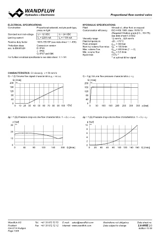
       CHARACTERISTICS  Oil viscosity  ν = 30 mm /s                                                                                                             229                                                          (1)
                                        2
       Q = f (I) Volume flow signal characteristics (p 3  = 100 bar)  Q = f (p) Volume flow pressure characteristics (I = I G )
          Q [l/min]                                            Q [l/min]                                                                                                                                          (1)
        200  K4098                                           200  K4097                                                            Dimensions of the other connection versions see data sheet 1.1-190
        160                                                  160                                                                                                                                         For detailed cavity drawing see data sheet
                                                                                                                                                                                                         2.13-1047
        120                                                  120
         80                                                   80
                                                                                                                                   PARTS LIST                                           ACCESSORIES
         40                                                   40                                                                    1          3        1                3              Line mount body Data sheet                 2.9-210
          0                                                    0                                                                    Position  Article  Description                      Proportional amplifier                  Register 1.13
                                                                                                                                       2
           0   10  20  30  40 50 60 70 80 90  100 I [%]         0    50  100  150  200  250  300  350 p [bar]                                        EN 175301                          Mating connector EN 175301-803     Article no. 219.2002
                                                                                                                                    10       206.3212  Solenoid coil WDE64 / 31 x 72-G12  Technical explanation see data sheet 1.0-100
                                                                                                                                             206.3213  Solenoid coil WDE64 / 31 x 72-G24
                                                                                                                                                             2
                                                                                                                                                     Junior-Timer
       Δp = f (Q) Pressure drop-volume flow characteristics  1→ 2 (I = 0 mA)  Δp = f (Q) Pressure drop-volume flow characteristics  1 → 3 (I = I G )
                                                                                                                                             206.3214  Solenoid coil WJE64/ 31 x 72-G12
          p [bar]                                              p [bar]                                                                       206.3215  Solenoid coil WJE64/ 31 x 72-G24
         30  K4096                                           10  K4095                                                                               Deutsch
                                                                                                                                             206.3216  Solenoid coil WGE64/ 31 x 72-G12
                                                              8                                                                              206.3217  Solenoid coil WGE64/ 31 x 72-G24
         20
                                                              6                                                                     15       253.8022  HC 8,5 anual override (data sheet 1.1-300)
         10                                                   4                                                                              239.2033  HB 0 Plug screw (data sheet 1.1-300)
                                                              2                                                                     17       160.2282  O-ring ID 28,24 x 2,62 (NBR)
                                                                                                                                    20       154.2706  Knurled nut
         0                                                    0
           0     40     80     120   160    200 Q [l/min]       0   20   40   60   80  100 120 140 160  Q [l/min]                   50       160.2377  O-ring ID 37,77 x 2,62 (NBR)
                                                                                                                                             160.8378  O-ring ID 37,77 x 2,62 (FKM)
                                                                                                                                    60       160.2329  O-ring ID 32,99 x 2,62 (NBR)
                                                                                                                                             160.6325  O-ring ID 32.99 x 2,62 (FKM)
                                                                                                                                    70       160.2314  O-ring ID 31,42x 2,62 (NBR)
                                                                                                                                             160.6315  O-ring ID 31,42x 2,62 (FKM)
                                                                                                                                    80       049.3384  Backup ring RD 33,5x 38 x 1,4
                                                                                                                                    90       049.3364  Backup ring RD 31,5x36x1,4


       Wandfluh AG        Tel.  +41 33 672 72 72   E-mail:  sales@wandfluh.com   Illustrations not obligatory   Data sheet no.     Wandfluh AG         Tel.  +41 33 672 72 72   E-mail:  sales@wandfluh.com   Illustrations not obligatory   Data sheet no.
       Postfach           Fax  +41 33 672 72 12   Internet:  www.wandfluh.com   Data subject to change   2.6-695E 2/3              Postfach            Fax  +41 33 672 72 12   Internet:  www.wandfluh.com   Data subject to change   2.6-695E 3/3
       CH-3714 Frutigen                                                                            Edition 15 08                   CH-3714 Frutigen                                                                             Edition 15 08
       Page 1306
   1301   1302   1303   1304   1305   1306   1307   1308   1309   1310   1311