
Page 1304 - Softbound_Edition_19_en
P. 1304
Proportional flow control valve Proportional flow control valves
Proportional flow control valve
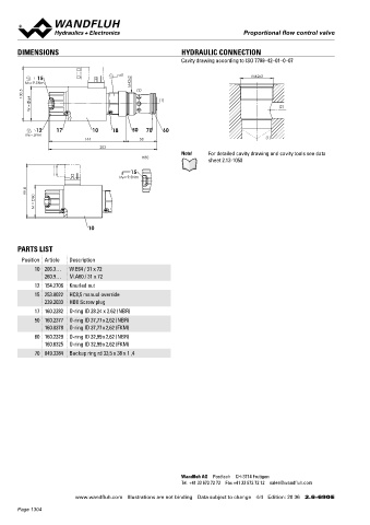
DIMENSIONS HYDRAULIC CONNECTION Proportional 3-way flow control valve
Cavity drawing according to ISO 7789–42–01–0–07 Screw-in cartridge
• Direct operated, pressure compensated M42 x 2
15 s41 M42x2 • Q = 200 l/min, p = 350 bar ISO 7789
MD=9.5Nm M42x2 • Q max = 160 l/min max
N max
100.5 64 (2) (1)
W = (2) DESCRIPTION FUNCTION APPLICATION
Direct operated, pressure compensated pro- The 3-way flow control valve serves for maintai- Proportional flow control valves are suitable for
portional flow control valve as a screw-in cart- ning the speed of a consumer constant inde- feed control systems, where the consumer flow
12 17 10 18 50 70 60 ridge with a thread M42 x 2 for cavity acc. to pendent of the load. Superfluous pump output has to be maintained constant with a changing
load. The screw-in cartridge is suitable for in-
flow is fed into the return flow system in a cost
ISO 7789. The volume flow is adjusted by a
MD=5Nm
144 58 (1) Wandfluh proportional solenoid (VDE standard saving manner, and as a result, prevents an stallation in control blocs.
0580). The cartridge body is made of steel. A overheating of the hydraulic system. The po-
203 special surface treatment guarantees a good wer controlled, proportional solenoid running
Note! For detailed cavity drawing and cavity tools see data
HB0 protection against corrosion and wear as well in oil acts directly on the throttle spool, which
sheet 2.13-1050 as very good low-friction characteristics of the opens the throttle segments in the cartridge
pressure compensating- and throttle spool. body. Proportional to the current demand of the
15 The solenoid coil is zinc- / nickel-coated. proportional solenoid, the throttle aperture
MD= 9.5Nm
changes, and with this the volume flow. In case
of a current-free solenoid, the throttle spool is
99.8 60 held in closed position by a spring. For driving
the valve, Wandfluh proportional amplifiers are
M = available (see Register 1.13).
TYPE CODE
10
Q D P PM42 - 160 - / W - #
Flow control valve
PARTS LIST 3-way
Position Article Description Proportional
10 206.3… W.E64 / 31 x 72 Screw-in cartridge M42 x 2
260.9… M.A60 / 31 x 72 Nominal volume flow rate Q N 160 l/min
12 154.2706 Knurled nut Nominal voltage U N 12 VDC G12
15 253.8022 HC8,5 manual override 24 VDC G24
X5
without coil
239.2033 HB0 Screw plug 10
Slip-on coil Metal housing, round M42x2
20
17 160.2282 O-ring ID 28.24 x 2.62 (NBR) Connection execution Connector socket EN 175301-803 / ISO 4400 D
s41
69
2 (T)
3 (A)
50 160.2377 O-ring ID 37,77 x 2,62 (NBR) 15 Connector socket AMP Junior-Timer J
160.8378 O-ring ID 37,77 x 2,62 (FKM) Connector Deutsch DT04-2P G 1 (P)
60 160.2329 O-ring ID 32,99 x 2,62 (NBR) Sealing material NBR
160.6325 O-ring ID 32,99 x 2,62 (FKM) 32 FKM (Viton) D1
70 049.3384 Backup ring rd 33,5 x 38 x 1 ,4 Manual override Screwed sealing plug HB0
Manual emergency actuation HC8.5
17 50 80 60 90 70
Design-Index (Subject to change)
1 88
138 90
229
SYMBOLS GENERAL SPECIFICATIONS
simplified detailed Description 3-way proportional flow control valve
Construction Screw-in cartridge for cavity acc. to ISO 7789
Operation Proportional solenoid
Mounting Screw-in thread M42 x 2
Ambient temperature -20…70 °C
1 3 Mounting position any
1 3 Fastening torque M = 100 Nm for screw-in cartridge
D
2 M = 5 Nm for knurled nut
D
Weight m = 2,34 kg
Flow direction see symbol
2
Wandfluh AG Postfach CH-3714 Frutigen
Tel. +41 33 672 72 72 Fax +41 33 672 72 12 sales@wandfluh.com
Wandfluh AG Tel. +41 33 672 72 72 E-mail: sales@wandfluh.com Illustrations not obligatory Data sheet no.
www.wandfluh.com Illustrations are not binding Data subject to change 4/4 Edition: 20 36 2.6-690 E Postfach Fax +41 33 672 72 12 Internet: www.wandfluh.com Data subject to change 2.6-695E 1/3
CH-3714 Frutigen Edition 15 08
Page 1304