
Page 1311 - Softbound_Edition_19_en
P. 1311
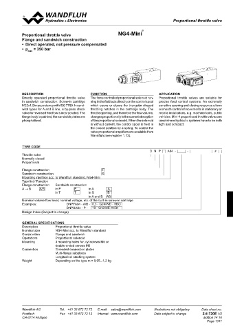
Proportional throttle valves                                                           Proportional throttle valves
                                                                                         Proportional throttle valve

 2
 CHARACTERISTICS Oil viscosityt υ = 30mm /s  Proportional throttle valve  nG4-Mini ®
 Q = f (p) Volume flow pressure characteristics  ∆p = f (Q)  Pressure loss/flow characteristic over non-return valve  Flange and sandwich construction
            •  Direct operated, not pressure compensated
 Q [l/min]  p [bar]  •  p   = 350 bar
 15  K0143  6  K0130  max
 12.5  Q  = 6.3 l/min  5
 N
 10  4
 7.5  Q  = 4 l/min  3
 N
 5  2
 2.5  1
 0  0
 0  50  100  150  200  250 p [bar]  0  1  2  3  4  5  6  7  8  Q [l/min]
 Q = f (I)  Volume flow adjustment characteristics  Q = f (I)  Volume flow adjustment characteristics
    DNP.A03     DOP.A03
 Q [l/min]  Q [l/min]  Description             FunCtion                           APPLiCAtion
                                               The force controlled proportional solenoid run-
            Directly  operated  proportional  throttle  valve
                                                                                  Proportional  throttle  valves  are  suitable  for
 8  K0142  8  K0141   = 6.3 l/min  in sandwich construction. Screw-in cartridge   ning in the fluid acts directly on the control spool   precise  feed  control  systems.  An  extremely
 7  Q N  = 6.3 l/min  7  Q N
 6  6       M22x1,5 in accordance with ISO 7789. In sand-  which opens or closes the triangular shaped   sensitive opening and closing response allows
 5  Q  = 4 l/min  5  Q  = 4 l/min  wich types for A and B line, a by-pass check   throttling  notches  in  the  cartridge  body. The   a smooth control of movements in stationary or
 N
 N
 4  4       valve for reversed free flow is incorporated. The   throttle opening, and therefore the flow volume,   mobile installations, e.g. machine tools, public
 3  3       flange body is painted, the sandwich plates are   changes proportionally to the current absorption   vehicles. Mini-4 proportional throttle valves are
 2  2       phosphatised.                      of the proportional solenoid. When the solenoid   used where hydraulic systems have to be both
 1  1                                          is without current, the control spool is held in   ligth and compact.
 0  0                                          the closed position by a spring. To control the
 0   10  20  30  40 50 60 70 80 90  100 l [%]  0   10  20  30  40 50 60 70 80 90  100 l [%]  valve proportional amplifiers are available from
                                               Wandfluh (see register 1.13).
 SYMBOLS / DIMENSIONS
 D.PFA03-A/B  D.PSA03-A  Flange construction D.PFA03-A/B  type coDe
                                                                              D  N  P   A04  -             -       #
 30
 15  10     Throttle valve
            Normally closed
            Proportional
 P
 D.PSA03-P  D.PSA03-B  Ø 7.5   Ø 4.2  ∗  T  A  B  To  30  Flange construction              F
                                                     S
            Sandwich construction
 15
            Mounting interface acc. to Wandfluh standard, NG4-Mini
 (8)  22  35  (19)  Type list / Function
 54         Flange construction   Sandwich construction
            A → B    A/B     in P      P      in A      A
                             in T      T      in B      B
 D.PSA03-T  D.PSA03-AB  15  Sandwich construction D.PSA03-P, T              in A and B  AB
            Nominal volume flow level, nominal voltage, etc. of the built-in screw-in cartridge
            Examples:              DNPFA04 - A/B -  6,3 - G24/WD - HBO
 P                                 DNPSA04 - P -   10 - G12/ME-A1D1
 A  B  30
 ∗  T  To   Design-Index (Subject to change)
 15
 Ø 4.2  48  (19)  GenerAL speciFicAtions
 30  67     Description       Proportional throttle valve
            Nominal size       NG4-Mini acc. to Wandfluh standard
 Sandwich construction D.PSA03-A, B, AB  Construction  Flange and sandwich
            Operations       Proportional solenoid
 PARTS LIST  A = 67  Mounting       3 mounting holes for. cyl.screws M5 or
                             double ended screws M5
   Position   Article    Description  P  Connection  Threaded connection plates
 A  B                        Multi-flange subplates
   10   160.2045   O-ring ID 4,5x1,50  ∗  T  To  30  ∗           Longitudinal stacking system
 15
            Weight           Depending on the type m = 0,95...1,2 kg
 SCREW-IN CARTRIDGES INSTALLED  48
 The following screw-in cartridges are used in either the flange body or   B = 67
 the sandwich body:
 AB = 96
 Type   Designation   Data sheet no.  ∗ The total lenghts depends on the cartridge type, see data
 D.PPM18   Proportional throttle valve   2.6-510    sheet 2.6-510

 ACCESSORIES
 Proportional amplifier   Register  1.13
 Technical explanation see data sheet 1.0-100

 Wandfluh AG   Tel.  +41 33 672 72 72   E-mail:  sales@wandfluh.com   Illustrations not obligatory   Data sheet no.   Wandfluh AG   Tel.  +41 33 672 72 72   E-mail:  sales@wandfluh.com   Illustrations not obligatory   Data sheet no.
 Postfach   Fax  +41 33 672 72 12   Internet:  www.wandfluh.com   Data subject to change   2.6-700E 2/2   Postfach   Fax  +41 33 672 72 12   Internet:  www.wandfluh.com   Data subject to change   2.6-720E 1/2
 CH-3714 Frutigen                   Edition 21 31  CH-3714 Frutigen                                      Edition 14 10
                                                                                                           Page 1311