Page 1360 - Softbound_Edition_19_en
P. 1360

AAHP6
 Ablasshahn
 Sandwichbauart
                                      NG6
  =   40 l/min
 • Q
 • p  max   = 350 bar   AAHA6      ISO 4401-03            AAHB6
 max
                         A
 BESCHREIBUNG  P T  B    FUNKTION      P T            B    A ANWENDUNG   P T            B        Drain valves                                                                                                        3-way shifting valves
 A
                                                                                                  Drain valve
 Ablasshahn in Sandwichbauart NG6 mit An-  Eine  gehärtete  Stahlkugel  sperrt  den  druck-  Diese Elemente werden in Anlagen mit Druck-
 schlussbild nach ISO 4401-03.  Es stehen  3  beaufschlagten Kanal zum Tank leckfrei ab.  speicher eingebaut. Für z. B. Revisionsarbeiten,
 ver-schiedene Standardausführungen zur Ver-  Durch Drehen am Verstellknopf kann dieser  kann  das  Speichersystem  mittels  des
       dIMENSIONS Stahl  ist
 fügung.  Der  Sandwichkörper  aus   zum Tank entlastet werden.  Der Verstellknopf  Ablasshahnes drucklos gemacht werden.          3-way shifting valve
 phosphatiert. Der Verstellknopf ist aus eloxier-  kann  mittels  Gewindestift  in  jeder  Position                                Screw-in cartridge
 tem Aluminium.          arretiert werden.                                                                                                                                         G1/2"
                                        5,5                                                                                        • Q max  = 20 l/min                       Wandfluh standard
                                                                                                                                   • p    = 210 bar
                                                                                                                                      max
 INHALT                  TYPENSCHLÜSSEL
                                                                      A     AH          6  /          #
 ALLGEMEINE KENNGRÖSSEN ................ 1        G3/8"
                         Internationale Anschlussnorm ISO  42        AAH.6/O                                                       DESCRIPTION                        FUNCTION
 HYDRAULISCHE KENNGRÖSSEN ........... 1                21                                                                          Shifting valve cartridge for cavity according   If  P-port  is  pressurised  oil  flows  to  A-port   APPLICATION
                                                                                                                                                                                                         See application example
                         Typenbezeichnung für Ablasshahn
 SCHALTZEICHEN/                                                                                                                    to Wandfluh standard. Port size G1/2". Valve   through the check valve mometed in the poppet
 TYPENAUFSTELLUNG .............................. 1  Ablasshahn:  P   T  P                                                          body made from steel. If P-part drilled from the   spool. Pressure drop over the check valve and
                                                                                                                                                                      area ratio P to A result in a force moving the
                                                                                                                                   side into the cavity port G1/2" may be plugged.
                                       A   T         A     10
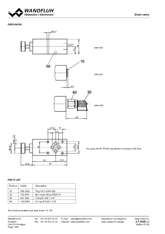
 ABMESSUNGEN ......................................... 2  B   T  B                                                                 Port G1/2" may also be used to screw a pipe   poppet spool auto its seat. T port is seald off
                                                                                                                                                                      leakfree. If P-port  is depressurised poppet
                                                                                                                                   ar hose fitting directly into it.
                                  50                                                                                                                                  spool will be pushed open by the pressure in
 ERSATZTEILLISTE ..................................... 2  Nenngrösse 6                                                                                                A-port. Flow passes from A to T. The check
                                                                                                                                                                      valve in the poppet spool prevents leak to
                         Gewindeanschluss offen      O               AAH.6/V                                                                                          P-port.
                         mit Verschlussschraube      V
                         mit Minimess-Schraubkupplung  M
                         Änderungs-Index (wird vom Werk eingesetzt)
                                                    4,2                                                                                                               TYPE CODE
                                                     40         30                                                                                                                                               DWW   404   -           /   2,5   #
 ALLGEMEINE KENNGRÖSSEN                    HYDRAULISCHE KENNGRÖSSEN
 Benennung  Ablasshahn                     Druckflüssigkeit    Mineralöle, andere Medien auf Anfrage                                                                  3-way shifting valve
 Nenngrösse  NG6 nach ISO 4401-03          Max. zulässiger Ver-  ISO 4406:1999, Klasse 20/18/14
 Bauart  Sandwichbauart                    schmutzungsgrad     (Empfohlene Filterfeinheit  ß 10...16≥75)                                                              Normal size 4
                                                                     AAH.6/M
 Befestigungsart  4 Befestigungslöcher für Zylinder-           siehe auch Datenblatt 1.0-50/2
        schrauben M5 oder Stiftschrauben M5  Viskositätsbereich  12 mm /s…320 mm /s                                                                                   Nominal volume flow rate Q    15 l/min       15
                                                                             2
                                                                    2
                                                                                                                                                                                          N
 Anschlussart  Gewindeanschlussplatte      Druckflüssigkeitstemperatur -20…+70°C                                                                                                             20 l/min         20
        Reihenflanschplatten und           Höchstdruck an
        Längenverkettungssystem            den Anschlüssen A, B, P  p max   =  350 bar
                                                        58
 Umgebungstemperatur  -20…+50°C            Höchstdruck an                                                                                                             Non-return valve, Opening pressure p ö   2,5 bar
 Einbaulage  beliebig                      Anschluss T         P max   =  50 bar
 Anzugsdrehmoment  M  = 5,5 Nm (Qualität 8.8)  Maximaler Volumenstrom  Q max  =  40 l/min                                                                             Design-Index (Subject to change)
          D
 Masse  m  = 1,5 kg                  21,5  19
                                        17,8
           2,5
 SCHALTZEICHEN / TYPENAUFSTELLUNG                                                                                                  GENERAL SPECIFICATIONS                               HYDRAULIC SPECIFICATIONS
           A,B=  P= 8                                                                                                              Description        3-way shifting valve              Fluid                  Mineral oil, other fluid on request
                                                                                                                                                      Screw-in cavity acc. to Wandfluh standard

                                                                                                                                                                                        Contamination efficiency-
                                                                                                                                   Construction
                                                                                                                                                                                                              ISO 4406:1999, class 18/16/13
         28                  31                        21  32,5  On types AAHB, P6 the adjustment is located on B-Side             Mounting           Screw-in thread G1/2"                                    (Required filtration grade ß6...10≥75)
                                                                                                                                   Ambient temperature
                                                                                                                                                      -20…+50 °C
                                                                                                                                                                                                               refer to data sheet 1.0-50/2
                                                                                                                                   Mounting position   any                              Visconsity range       12 mm /s…320 mm /s
                                                                                                                                                                                                                            2
                                                                                                                                                                                                                   2
                                                                                                                                   Fastening torque   M  = 60 Nm                        Fluid temperature      -20…+70 °C
                                                                                                                                                       D
                                                                                                                                   Weight             m = 0,04 kg                       Peak pressure          p  = 210 bar
                                                                                                                                                       T
                                65          ( 32)                                                                                                                                       Opening pressure over       max
                   32,5             97                                                                                                                                                  non-return valve       p  = 2,5 bar
                                                                                                                                                                                                               ö
                                                                                                                                                                                        Norminal volume flow       Q  = 15 l/min
                                                                                                                                                                                                               N
                                                                                                                                            A                         P                 at ∆p 10 bar           Q  = 20 l/min
                                                                                                                                                                                                               N
                                                                                                                                                                           G  1/2"      Area ratio of the innner spool  P : A = 1,2 : 1
                                                                                                                                                                                                               Q
                                                                                                                                                                                                                 = 20 l/min
                                                                                                                                                                                        Max. volume flow
                                                                                                                                                                                                               max
       PARTS LIST
         Position   Article   Description                                                                                          SYMBOLS                                              CONTROL MECHANICAL
                                                                                                                                                                                        Fixed setting
         10     238.3202   Plug VSTI G3/8"-ED                                                                                            simplified              detailed
         30     152.9101   Mini-mess fitting 1620/1/4"
         40     241.1621    Fitting RI 3/8" x 1/4"                                                                                              A                     T
         50     160.2093   O-ring ID 9,25 x 1,78
                                                                                                                                        T             P       A                    P
       Technical explanation see data sheet 1.0-100
       Wandfluh AG        Tel.  +41 33 672 72 72   E-mail:  sales@wandfluh.com   Illustrations not obligatory   Data sheet no.     Wandfluh AG         Tel.  +41 33 672 72 72   E-mail:  sales@wandfluh.com   Illustrations not obligatory   Data sheet no.
       Postfach           Fax  +41 33 672 72 12   Internet:  www.wandfluh.com   Data subject to change   2.7-160E 2/2              Postfach            Fax  +41 33 672 72 12   Internet:  www.wandfluh.com   Data subject to change   2.7-180E 1/2
       CH-3714 Frutigen                                                                            Edition 03 26                   CH-3714 Frutigen                                                                             Edition 18 28
       Page 1360
                                                                                                                                                                        10    20
                                                                                                                                                                               T
                                                                                                                                                 3                       A                  P    G  1/2"


                                                                                                                                                                                  27


                                                                                                                                                               Poppet valve 2/2-way
                                                                                                                                                               Sitzventil 2/2-Wege
                                                                                                                                                               Valve à clapet 2/2-voies
   1355   1356   1357   1358   1359   1360   1361   1362   1363   1364   1365