
Page 1354 - Softbound_Edition_19_en
P. 1354
Pipe failure valves Pipe failure valves
Pipe failure valve
2
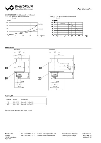
CHARACTERISTICS Oil viscosity υ = 30 mm /s
∆p = f (Q) Pressure drop characteristic Q = f (n) Cut-off volume flow characteristic Pipe failure valve
P → A A → P For installation in pipes
p [bar] • Q max = 30 l/min NG10
20 K0530 • p max = 210 bar
RBSW638
15
10 A RBSG638 DESCRIPTION FUNCTION APPLICATION
5 P A Pipe failure valve NG10 for line mounting. The Fluid can pass the valve in both flow directions. Pipe failure valves are used where loads must
In flow direction A to P the valve closes if the
valve is screwed directly into the component
be protected against uncontrolled lowering
0 which has to be protected. Thread size for amount of flow exceeds the adjusted value. after a line rupture, for exemple in scissor lifts
0 5 10 15 P 20 Q [l/min] port A: male G1/2". For port P: female G3/8" Amount of flow which causes the valve to close or leveling platforms.
for type RBSG1012 or female G1/2" for type (cut-off flow) can be adjusted by means of an Caution:
RBSW1012. This pipe failure valve is availab- adjustment screw. The valve is set at 20–25 l/min Pipe failure valves are nor suitable for appli-
le in a straight version and in a 90° version. (at the factory. Turning the adjustment screw cations where pressure and flow changes
Housing and banjo bolt are zinc coated. clockwise reduces the cut-off flow. rapidly under normal working conditions.
DIMENSIONS
RBSG638 RBSW638
s27 s27
G1/4" 27 TYPE CODE
P RBS 10 12 #
9 9
Pipe failure valve
Straight execution G
P G3/8" Angled execution W
10 30 30 10 30 Breite 30
17,5 Nominal size 10
Threaded connection G1/2"
G3/8" 17,5 max. G3/8" max. Design-Index (subject to change)
10 A 20 A 17,5
s2,5 s2,5
GENERAL SPECIFICATIONS HYDRAULIC SPECIFICATIONS
s8 s8 Description Pipe failure valve Fluid Mineral oil, other fluid on request
Construction Threaded body Contamination efficiency ISO 4406:1999, class 20/18/14
27 25,7 Mounting Threaded port, line mounting (Required filtration grade ß 10...25≥75)
44 Connections Threaded port male G1/2" refer to data sheet 1.0-50/2
Threaded port female G3/8" (RBSG1012) Viscosity range 12mm /s...320mm /s
2
2
Threaded port female G1/2" (RBSW1012) Fluid temperature -20...+70°C
Ambient temperature -20..+50°C Peak pressure p max = 210 bar
PARTS LIST Mounting position any Max. volume flow P → A: Q max = 30 l/min
Weight RBSG1012 m = 0,26 kg A → P: Q max = 35 l/min
RBSW1012 m = 0,38 kg
Position Article Description
10 160.2215 O-ring ID 21,00x1,50
20 160.2188 O-ring ID 18,77x1,78
SYMBOLS
simplified detailed
Technical explanation see data sheet 1.0-100
A
P A
P
Wandfluh AG Tel. +41 33 672 72 72 E-mail: sales@wandfluh.com Illustrations not obligatory Data sheet no. Wandfluh AG s32 Tel. +41 33 672 72 72 E-mail: sales@wandfluh.com Illustrations not obligatory Data sheet no.
s32
Postfach Fax +41 33 672 72 12 Internet: www.wandfluh.com Data subject to change 2.7-130E 2/2 Postfach Fax +41 33 672 72 12 Internet: www.wandfluh.com Data subject to change 2.7-140E 1/2
0CH-3714 Frutigen Edition 03 26 CH-3714 Frutigen G3/8" 32 Edition 09 51
Page 1354
P
10 10
P G1/2"
10 35 34 10 20 34 Breite 40
23 max. 23 max.
G1/2" G1/2"
A A
20 10
s3 s3
s10 s10
32 31,5
52