
Page 1353 - Softbound_Edition_19_en
P. 1353
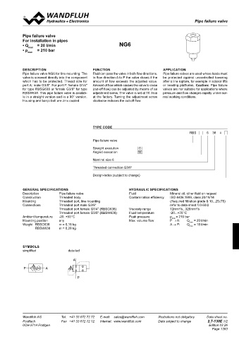
Pipe failure valve
 Shuttle valves                                                                                  Pipe failure valves

 characteriSticS   Oil viscosity υ = 30 mm /s  Pipe failure valve
 2
 ∆p = f (Q)   Pressure loss - volume flow - curve  For installation in pipes
    P1 → A and P2 → A     • Q     = 20 l/min                NG6
 p[bar]        max
 5  K0490   • p max    = 210 bar
 4
 3
 2          DESCRIPTION                        FUNCTION                           APPLICATION
 1          Pipe failure valve NG6 for line mounting. The   Fluid can pass the valve in both flow directions.   Pipe failure valves are used where loads must
            valve is screwed directly into the component   In flow direction A to P the valve closes if the   be  protected  against  uncontrolled  lowering
 0          which has to be protected. Thread size for   amount of flow exceeds the adjusted value.   after a line rupture, for exemple in scissor lifts
 0  10  20  30  40  Q [l/min]  port A: male G3/8". For port P: female G1/4"   Amount of flow which causes the valve to close   or  leveling  platforms. Caution:  Pipe  failure
 dimenSionS  for type RBSG638 or female G3/8" for type   (cut-off flow) can be adjusted by means of an   valves are nor suitable for applications where
            RBSW638. This pipe failure valve is availab-  adjustment screw. The valve is set at 10 l/min   pressure and flow changes rapidly under nor-
            le in a straight version and in a 90° version.   at the factory. Turning the adjustment screw   mal working conditions.
 26  G3/8"  Housing and banjo bolt are zinc coated.  clockwise reduces the cut-off flow.
 26  G3/8"


 A
 A
 5                                             TYPE CODE
 17  M
 5
 17  M                                                                                         RBS      6  38  #
 37,5                                          Pipe failure valve
 37,5
 55                                            Straight execution     G
 55                                            Angled execution       W
 P1  P2
 P1  P2                                        Nominal size 6

 17,5                                          Threaded connection G3/8"
 17,5
                                               Design-Index (subject to change)


 12  35  12  G3/8"  GENERAL SPECIFICATIONS                       HYDRAULIC SPECIFICATIONS
 12  35  12  G3/8"  Description   Pipe failure valve             Fluid                Mineral oil, other fluid on request
 application example  Construction   Threaded body               Contamination efficiency   ISO 4406:1999, class 20/18/14
 A          Mounting          Threaded port, line mounting                            (Required filtration grade ß 10...25≥75)
 A          Connections       Threaded port male G3/8"                                refer to data sheet 1.0-50/2
                              Threaded port female G1/4" (RBSG638)  Viscosity range    12mm /s...320mm /s
                                                                                          2
                                                                                                   2
                              Threaded port female G3/8" (RBSW638)  Fluid temperature   -20...+70 °C
 P1  P2     Ambient temperature   -20..+50 °C                    Peak pressure        p  = 210 bar
                                                                                       max
 P1  P2     Mounting position   any                              Max. volume flow     P → A:   Q max  = 20 l/min
 A          Weight  RBSG638   m = 0,18 kg                                             A → P:   Q max  = 18 l/min
 A  P1  P2         RBSW638    m = 0,28 kg
 P1  P2

            SYMBOLS
 A  B       simplified             detailed
 A  B
 a  b                                 A
 a  b  P  T
 P  T        P          A


                                        P


 Technical explanation see data sheet 1.0-100


                     s27                                      s27
 Wandfluh AG   Tel.  +41 33 672 72 72   E-mail:  sales@wandfluh.com   Illustrations not obligatory   Data sheet no.   Wandfluh AG   Tel.  +41 33 672 72 72   E-mail:  sales@wandfluh.com   Illustrations not obligatory   Data sheet no.
 Postfach   Fax  +41 33 672 72 12   Internet:  www.wandfluh.com   Data subject to change   2.7-120E 2/2   Postfach  G1/4"  Fax  +41 33 672 72 12   Internet:  www.wandfluh.com   Data subject to change   2.7-130E 1/2
                                                                    27
 CH-3714 Frutigen                   Edition 03 26  0CH-3714 Frutigen                                     Edition 03 26
                    P                                                                                      Page 1353
                                 9                                                   9

                                                                           P   G3/8"
    10                30         30         10                                       30  Breite 30
                                                                                  17,5


                    G3/8"        17,5 max.                    G3/8"                  max.
    10            A                         20              A                        17,5

                        s2,5                                      s2,5
                     s8                                        s8
                      27                                       25,7
                                                                 44