
Page 1287 - Softbound_Edition_19_en
P. 1287
Proportional flow control valves Proportional flow control valves
Proportional flow control valve
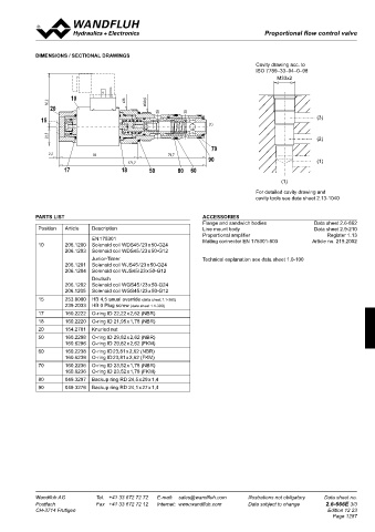
ELECTRICAL SPECIFICATIONS HyDRAuLIC SPECIFICATIONS DImENSIONS / SECTIONAL DRAwINGS
Construction Proportional solenoid, wet pin push type, Fluid Mineral oil, other fluid on request Cavity drawing acc. to
pressure tight Contamination efficiency ISO 4406:1999, class 18/16/13 ISO 7789–33–04–0–98
Standard nominal voltage U = 12 VDC U = 24 VDC (Required filtration grade β 6…10 ≥ 75) M33x2
see data sheet 1.0-50/2
Limiting current I = 1560 mA I = 780 mA Viscosity range 12 mm /s…320 mm /s
2
2
G
G
Relative duty factor 100 % ED / DF (see data sheet 1.1- 430) Fluid temperature -20…+70 °C
Protection class Connection version Peak pressure p max = 350 bar 62,2 10 s36 M33x2
= 32 l/min, 63 l/min
acc. to EN 60 529 D: IP 65 Nominal volume flow rates Q N = 100 l/min (1 → 2) 20
Max. volume flow
Q
J: IP 66 Min. volume flow max = 0,4 l/min (3) (2)
G: IP 67 and 69K Hysteresis Q min 15 (3)
≤ 5 % ٭
For further electrical specifications see data sheet 1.1-180 (W) ٭ at optimal dither signal (1)
1.1-181 (M) 22,5 (2)
70
2,2 92 79,7
CHARACTERISTICS Oil viscosity ν = 30 mm /s 171,7 90 (1)
2
Q = f (I) Volume flow adjustment characteristics 1 → 3 (p 3 = 100 bar) Q = f (p) Volume flow pressure characteristics (I = I G ) 17 18 50 80 60
Q [l/min] Q [l/min] (1)
100 K0985 100 K0986
80 For detailed cavity drawing and
Q = 63 l/min 80 cavity tools see data sheet 2.13-1040
N
60 60 Q = 63 l/min
N
Q N = 32 l/min
40 40 PARTS LIST ACCESSORIES
20 20 Q = 32 l/min Flange and sandwich bodies Data sheet 2.6-862
N
0 0 Position 1 Article 3 Description Line mount body Data sheet 2.9-210
0 10 20 30 40 50 60 70 80 90 100 I [%] 0 50 100 150 200 250 300 350 p [bar] EN 175301 1 3 Proportional amplifier Register 1.13
10 206.1200 Solenoid coil WDS45 / 23 x 50-G24 Mating connector EN 175301-803 Article no. 219.2002
2
206.1203 Solenoid coil WDS45 / 23 x 50-G12
Junior-Timer Technical explanation see data sheet 1.0-100
Δp = f (Q) Pressure drop-volume flow characteristics 1→ 2 (I = 0 mA) Δp = f (Q) Pressure drop-volume flow characteristics 1 → 3 (I = I G )
206.1201 Solenoid coil WJS45 / 23 x 50-G24
2
206.1204 Solenoid coil WJS45/ 23 x 50-G12
p [bar] p [bar]
30 K0987 30 K0988 Deutsch
Q = 32 l/min 206.1202 Solenoid coil WGS45 / 23 x 50-G24
25 25 N 206.1205 Solenoid coil WGS45 / 23 x 50-G12
20 20 15 253.8000 HB 4,5 anual override (data sheet 1.1-300)
15 15 Q = 63 l/min 239.2033 HB 0 Plug screw (data sheet 1.1-300)
10 10 N 17 160.2222 O-ring ID 22,22 x 2,62 (NBR)
5 5 18 160.2220 O-ring ID 21,95 x 1,78 (NBR)
0 0
0 20 40 60 80 100 Q [l/min] 0 10 20 30 40 50 60 70 80 Q [l/min] 20 154.2701 Knurled nut
50 160.2298 O-ring ID 29,82 x 2,62 (NBR)
160.6296 O-ring ID 29,82 x 2,62 (FKM)
60 160.2238 O-ring ID 23,81 x 2,62 (NBR)
160.6238 O-ring ID 23,81 x 2,62 (FKM)
70 160.2236 O-ring ID 23,52 x 1,78 (NBR)
160.6236 O-ring ID 23,52 x 1,78 (FKM)
80 049.3297 Backup ring RD 24,5 x 29 x 1,4
90 049.3276 Backup ring RD 24,1 x 27 x 1,4
Wandfluh AG Tel. +41 33 672 72 72 E-mail: sales@wandfluh.com Illustrations not obligatory Data sheet no. Wandfluh AG Tel. +41 33 672 72 72 E-mail: sales@wandfluh.com Illustrations not obligatory Data sheet no.
Postfach Fax +41 33 672 72 12 Internet: www.wandfluh.com Data subject to change 2.6-666E 2/3 Postfach Fax +41 33 672 72 12 Internet: www.wandfluh.com Data subject to change 2.6-666E 3/3
CH-3714 Frutigen Edition 12 23 CH-3714 Frutigen Edition 12 23
Page 1287