
Page 1292 - Softbound_Edition_19_en
P. 1292
Proportional flow control valves Proportional flow control valves
Proportional flow control valve
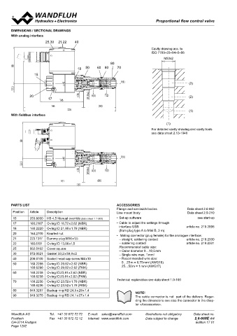
DIMENSIONS / SECTIONAL DRAWINGS
With analog interface Proportional 3-way flow control valve
Screw-in cartridge
5
25,30 21,22 40 1 /16″-12 UN
• Direct operated, pressure compensated
Cavity drawing acc. to Wandfluh standard
X2 • Q = 100 l/min, p = 350 bar
ISO 7789–33–04–0–98 max max
X1 • Q N max = 63 l/min
M33x2
80
88 50 60 80 70
18 DESCRIPTION FUNCTION APPLICATION
15 Direct operated, pressure compensated pro- The 3-way flow control valve serves for maintai- Proportional flow control valves are suitable for
portional flow control valve as a screw-in cart- ning the speed of a consumer constant inde- feed control systems, where the consumer flow
5
P(1) ridge with a thread 1 / 16″-12 UN for cavity acc. pendent of the load. Superfluous pump output has to be maintained constant with a changing
45 (3) to Wandfluh standard. Two flow ranges are flow is fed into the return flow system in a cost load. The screw-in cartridge is suitable for in-
22.5 available. The volume flow is adjusted by a saving manner, and as a result, prevents an stallation in control blocs.
Wandfluh proportional solenoid (VDE standard
overheating of the hydraulic system. The po-
20 s 36 M 33x2 A(3) T(2) (2) 0580). The cartridge body is made of steel. A wer controlled, proportional solenoid running
17 106 special surface treatment guarantees a good in oil acts directly on the throttle spool, which
protection against corrosion and wear as well opens the throttle segments in the cartridge
146 (80) as very good low-friction characteristics of the body. Proportional to the current demand of the
226 (1) pressure compensating- and throttle spool. proportional solenoid, the throttle aperture
With fieldbus interface The solenoid coil is zinc- /nickel-coated. changes, and with this the volume flow. In case
of a current-free solenoid, the throttle spool is
(1) held in closed position by a spring. For driving
X2 the valve, Wandfluh proportional amplifiers are
For detailed cavity drawing and cavity tools
X1 available (see Register 1.13).
see data sheet 2.13-1040
88 X3 TYPE CODE
Q D P PU16 - - / - #
Flow control valve
45 P(1) 3-way
22.5 Proportional
s 36 M 33x2 A(3) T(2) Screw-in cartridge 1 / 16″-12 UN
5
Nominal volume flow rate Q N 32 l/min 32
101 (80) 63 l/min 63
181 12 VDC G12
Nominal voltage U N
24 VDC G24
without coil X5
1-5/16"-12UN-2A
Slip-on coil Metal housing, round W 1-5/16"-12UN-2B
Metal housing, square M
PARTS LIST ACCESSORIES 62,2 10 s36
Flange and sandwich bodies Data sheet 2.6-862 20 Connection execution Connector socket EN 175301-803 / ISO 4400 D
(3)
Position Article Description Line mount body Data sheet 2.9-210 Connector socket AMP Junior-Timer J
(2)
15 253.8000 HB 4,5 Manual override (data sheet 1.1-300) • Set-up software see start-up 15 Sealing material Connector Deutsch DT04-2P G 3
(1)
NBR
17 1 160.2187 O-ring ID 18,72 x 2,62 (NBR) 3 • Cable to adjust the settings through FKM (Viton) D1
3
1
18 2 160.2220 O-ring ID 21,95 x 1,78 (NBR) interface USB article no. 219.2896 22,6 Manual override Armature tube closed (standard)
(from plug type A to Mini B, 3 m)
20 154.2700 Knurled nut • Mating connector (plug female) for the analogue interface: Screwed sealing plug HB0 2
21 223.1317 Dummy plug M16 x1,5 – straight, soldering contact article no. 219.2330 2,9 95,2 Manual emergency actuation 70 HB4.5
75,8
2
22 160.6131 O-ring ID 13,00 x1,5 – soldering contact article no. 219.2331 Design-Index (Subject to change) 1
171
25 062.0102 Cover square Recommended cable size: 17 18 50 60 80 90
– Outer diameter 9…10,5 mm
30 072.0021 Gasket 33,2 x 59,9 x 2 – Single wire max. 1 mm 2
40 208.0100 Socket head cap screw M4 x10 – Recommended wire size:
2
50 160.2298 O-ring ID 29,82 x 2,62 (NBR) 0…25 m = 0,75 mm (AWG18) SYMBOLS GENERAL SPECIFICATIONS
2
160.6296 O-ring ID 29,82 x 2,62 (FKM) 25…50 m = 1 mm (AWG17) simplified detailed Description 3-way proportional flow control valve
60 160.2238 O-ring ID 23,81 x 2,62 (NBR) Construction Screw-in cartridge for cavity according to
160.6238 O-ring ID 23,81 x 2,62 (FKM) Wandfluh Standard
70 160.2236 O-ring ID 23,52 x 1,78 (NBR) Technical explanation see data sheet 1.0-100 Operation Proportional solenoid
Screw-in thread 1 / 16″-12 UN
Mounting
5
160.6236 O-ring ID 23,52 x 1,78 (FKM) 1 3 Ambient temperature -25…50 °C
80 049.3297 Backup ring RD 24,5 x 29 x 1,4 NOTE! 1 3 Mounting position any
90 049.3276 Backup ring RD 24,1 x 27 x 1,4 The cable connector is not part of the delivery. Regar- 2 Fastening torque M = 80 Nm for screw-in cartridge
D
D
ding the dimensions see also the connector in the chap- Weight M = 7 Nm for knurled nut
m = 1,00 kg
ter «Accessories».
2 Flow direction see symbol
Wandfluh AG Tel. +41 33 672 72 72 E-mail: sales@wandfluh.com Illustrations not obligatory Data sheet no. Wandfluh AG Tel. +41 33 672 72 72 E-mail: sales@wandfluh.com Illustrations not obligatory Data sheet no.
Postfach Fax +41 33 672 72 12 Internet: www.wandfluh.com Data subject to change 2.6-668E 4/4 Postfach Fax +41 33 672 72 12 Internet: www.wandfluh.com Data subject to change 2.6-670E 1/3
CH-3714 Frutigen Edition 17 01 CH-3714 Frutigen Edition 11 13
Page 1292