
Page 1269 - Softbound_Edition_19_en
P. 1269
Proportional flow control valve
Proportional flow control valve
PERFORMANCE SPECIFICATIONS
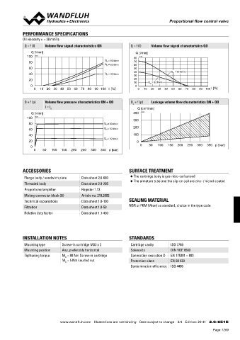
Oil viscosity u = 30 mm /s
2
Q = f (I) Volume flow signal characteristics QN Q = f (I) Volume flow signal characteristics QO
Q [l/min] Q [l/min]
100 K0978 80 K4164
Q = 80 l/min
80 N 70
Q = 63 l/min 60
N
60 50
40 Q N = 63 l/min
40 Q N = 32 l/min 30
20 20
10 Q N = 32 l/min
0 0
0 10 20 30 40 50 60 70 80 90 100 I [%] 0 10 20 30 40 50 60 70 80 90 100 I [%]
Q = f (p) Volume flow pressure characteristics QN + QO Q = f (p) Leakage volume flow characteristics QN + QO
L
I = I G Q [cm /min]
3
Q [l/min] 400 K0980
100 K0979
300
80 Q = 80 l/min
N
60 Q = 63 l/min 200
N
40 100
Q N = 32 l/min
20 0
0 0 50 100 150 200 250 300 350 p [bar]
0 50 100 150 200 250 300 350 p [bar]
ACCESSORIES SURFACE TREATMENT
Flange body / sandwich plate Data sheet 2.6-680 ◆ The cartridge body is gas-nitro-carburised
◆ The armature tube and the slip-on coil are zinc- / nickel-coated
Threaded body Data sheet 2.9-205
Proportional amplifier Register 1.13
Mating connector black (B) Article no. 219.2002
Technical explanations Data sheet 1.0-100 SEALING MATERIAL
Filtration Data sheet 1.0-50 NBR or FKM (Viton) as standard, choice in the type code
Relative duty factor Data sheet 1.1-430
INSTALLATION NOTES STANDARDS
Mounting type Screw-in cartridge M33 x 2 Cartridge cavity ISO 7789
Mounting position Any, preferably horizontal Solenoids DIN VDE 0580
Tightening torque M = 80 Nm Screw-in cartridge Connection execution D EN 175301 – 803
D
M = 5 Nm knurled nut Protection class EN 60 529
D
Contamination efficiency ISO 4406
www.wandfluh.com Illustrations are not binding Data subject to change 3/4 Edition: 20 41 2.6-651 E
Page 1269