
Page 1265 - Softbound_Edition_19_en
P. 1265
Proportional flow control valve
Proportional flow control valves Proportional flow control valves
ELECTRICAL SPECIFICATIONS HYDRAULIC SPECIFICATIONS DIMENSIONS / SECTIONAL DRAWINGS
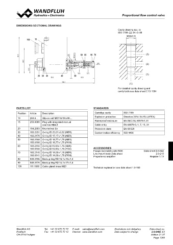
Construction 10 Proportional solenoid, wet pin push type, Fluid Mineral oil, other fluid on request Cavity drawing acc. to
100
pressure tight Contamination efficiency ISO 4406:1999, class 18/16/13 ISO 7789–22–04–0–98
Standard nominal voltage U = 12 VDC, 24 VDC (Recommended filtration grade
N
12VDC 24VDC ß 6...10 ≥ 75) M22x1,5
Limiting current L15/50 °C I = 950 mA 450 mA see data sheet 1.0-50/2 100 10
G
L15/70 °C I G = 910 mA 420 mA Viscosity range 12 mm /s…320 mm /s
2
2
s30
93.3 Voltage tolerance + 10% of rated voltage M22x1.5 60 80 90 70 Fluid temperature -25…+70 °C (operation as T1…T4 / T130 °C)
Relative duty factor 100% ED Peak pressure p max = 350 bar
Protection class IP67 acc. to EN 60 529 Nominal volume flow Q = 8/16/25 l/min
64.5
N
Connection / Power supply Through cable gland for 1(P) Max. Volume flow Q max = 40 l/min (1 →2) 60 80 90 70 (3)
cable ∅ 6,5…14 mm Min. Volume flow Q = 0,1 l/min 93.3 s30 M22x1.5
min
Temperature class: T1…T4 (acc. to EN 60079-0) Leakage volume flow see characteristics
22.5
Nominal power: 15W 3(A) 2(T) Repeatability ≤ 3 %* 64.5
For further electrical characteristics, refer to the data sheet of the so- Hysteresis ≤ 7 %* 1(P) (2)
30
20
50
40
40
lenoid coil: 1.1-183 95.6 60.5 * at optimal dither signal
22.5
156.1
3(A) 2(T) (1)
20 30 40 40 50
SYMBOLS SECURITY OPERATED 95.6 60.5
simplified detailed The solenoid coil must only be put into operation, if the re- 156.1
quirements of the operating instructions supplied are obser- (1)
ved to their full extent. For detailed cavity drawing and
In case of non-observance, no liability can be assumed. cavity tools see data sheet 2.13-1004
1 3
1 3 INSTALLATION
2 For stack assembly please observe the remarks in the operating in-
structions. 1 3
PARTS LIST 1 3 STANDARDS
2 2
Position Article Description Cartridge cavity ISO 7789
Explosion protection Directive 2014 / 34 / EU (ATEX)
10 263.6... Slip-on coil MKY45/18 x 60-...
CHARACTERISTICS Oil viscosity ν = 30 mm /s 15 253.8000 Plug with integrated manual Flameproof enclosure EN / IEC / UL 60079-1,31
2
2
Q = f (I) Volume flow adjustment characteristics 1 → 3 (p 3 = 200 bar) Q = f (p) Volume flow pressure characteristics (I = I G ) override HB4,5 Cable entry EN 60079-0, 1, 7, 15, 31
Q [l/min] Q [l/min] 20 154.2603 Knurled nut Ex Protection class EN 60 529
30 K1178 Q = 25 l/min 40 K1179 30 160.2251 O-ring ID 25,07 x 2,62 (NBR) Contamination efficiency ISO 4406
N
25 30 Q = 25 l/min 40 160.2170 O-ring ID 17,17 x 1,78 (NBR)
N
20 Q = 16 l/min 50 160.2188 O-ring ID 18,77 x 1,78 (NBR)
N
N
15 Q = 8 l/min 20 Q = 16 l/min 160.6188 O-ring ID 18,77 x 1,78 (FKM)
N
10 10 Q = 8 l/min 60 160.2156 O-ring ID 15,60 x 1,78 (NBR)
N
5 160.6156 O-ring ID 15,60 x 1,78 (FKM) ACCESSORIES
0 0 70 160.2140 O-ring ID 14,00 x 1,78 (NBR) Flange-/sandwich plate NG6 Data sheet 2.6-842
2.9-210
0 10 20 30 40 50 60 70 80 90 100 I [%] 0 50 100 150 200 250 300 350 p [bar] 160.6141 O-ring ID 14,00 x 1,78 (FKM) Line mount body Data sheet Register 1.13
Proportional amplifier
80 049.3196 Backup ring RD 16,1 x 19 x 1,4
90 049.3176 Backup ring RD 14,1 x 17 x 1,4
Δp = f (Q) Pressure drop-volume flow characteristics 1→ 2 (I = 0 mA) Δp = f (Q) Pressure drop-volume flow characteristics 1 → 3 (I = I G ) 100 111.1080 Cable gland brass M20
Technical explanation see data sheet 1.0-100
p [bar] p [bar]
Q = 8 l/min Q = 16 l/min Q = 25 l/min
30 K0968 25 K0969_1 N N N
25 20
20 15
15
10 10
5 5
0 0
0 5 10 15 20 25 30 35 40 Q [l/min] 0 5 10 15 20 25 30 Q [l/min]
Wandfluh AG Tel. +41 33 672 72 72 E-mail: sales@wandfluh.com Illustrations not obligatory Data sheet no. Wandfluh AG Tel. +41 33 672 72 72 E-mail: sales@wandfluh.com Illustrations not obligatory Data sheet no.
Postfach Fax +41 33 672 72 12 Internet: www.wandfluh.com Data subject to change 2.6-648E 2/3 Postfach Fax +41 33 672 72 12 Internet: www.wandfluh.com Data subject to change 2.6-648E 3/3
CH-3714 Frutigen Edition 21 37 CH-3714 Frutigen Edition 21 37
Page 1265