
Page 1262 - Softbound_Edition_19_en
P. 1262
Proportional flow control valve
Proportional flow control valves Proportional flow control valves
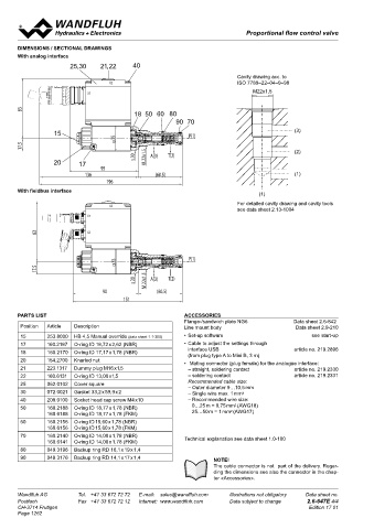
DIMENSIONS / SECTIONAL DRAWINGS M22x1,5
With analog interface Proportional 3-way flow control valve ISO 7789
25,30 21,22 40 Screw-in cartridge II 2 G Ex db IIC T6, T4
• Direct operated, pressure compensated
Cavity drawing acc. to • Q = 40 l/min, p = 350 bar II 2 D Ex tb III C T80 °C, T130 °C
X2 ISO 7789–22–04–0–98 • Q max = 25 l/min max I M2 Ex db I Mb
M22x1,5 N max
X1 Class I Division 1
Class I Zone 1
83 DESCRIPTION FUNCTION APPLICATION
18 50 60 80 For explosion-hazard zones The 3-way flow control valve serves for maintai- Proportional flow control valves are suitable for
90 70 Direct operated, pressure compensated pro- ning the speed of a consumer constant inde- feed control systems, where the consumer flow
pendent of the load. Superfluous pump output
has to be maintained constant with a changing
portional flow control valve, as a screw-in
15 P(1) (3) cartridge with a thread M22 x 1,5 for cavity flow is fed into the return flow system in a cost load. These valves are suitable for applications
35 acc. to ISO 7789. A special surface treatment saving manner, and as a result, prevents an in explosion-hazard zones, open cast and also
17.5 (2) guarantees a good protection against corro- overheating of the hydraulic system. The po- in mines. The facility for electric remote con-
wer controlled, proportional solenoid running
sion and wear as well as very good low-fric-
trolling of the valve in conjunction with process
s 30 M 22x1.5 A(3) T(2) tion characteristics of the pressure compen- in oil acts directly on the throttle spool, which control systems enables economic problem so-
20 17 sating- and throttle spool. The solenoid coil is opens the throttle segments in the cartridge lutions with repeatable sequences. Installation
95 zinc- / nickel-coated. body. Proportional to the current demand of the of the screw-in cartridge in control blocks.
136 (60.5) (1) The flameproof enclosures prevents an explo- proportional solenoid, the throttle aperture
196 sion in the interior from getting outside. changes, and with this the volume flow. In case
The design prevents a surface temperature of a current-free solenoid, the throttle spool is
With fieldbus interface
(1) capable of igniting. held in closed position by a spring. For driving
the valve, Wandfluh proportional amplifiers are
For detailed cavity drawing and cavity tools
X2 available (see Register 1.13).1.13).
see data sheet 2.13-1004
X1
TYPE CODE
83 X3 Q D B PM22 - - / L15 / - #
Flow control valve
3-way
P(1) Proportional, Explosion proof execution Ex d
35
17.5 Screw-in cartridge M22x1,5
8 l/min
8
s 30 M 22x1.5 A(3) T(2) Nominal volume flow rate Q N 16 l/min 16
90 (60.5) 25 l/min 25
151 Nominal voltage U N 12 VDC G12
24 VDC G24
Ambient temp. by:
PARTS LIST ACCESSORIES Nominal power P 15W 70 °C
Flange-/sandwich plate NG6 Data sheet 2.6-842 N
Position Article Description Line mount body Data sheet 2.9-210 Certificate ATEX, IECEx, CCC, EAC UL / CSA UL MA MA
15 253.8000 HB 4,5 Manual override (data sheet 1.1-300) • Set-up software see start-up Sealing material Australia AU
NBR
17 160.2187 O-ring ID 18,72 x 2,62 (NBR) • Cable to adjust the settings through FKM (Viton) D1
18 160.2170 O-ring ID 17,17 x 1,78 (NBR) interface USB article no. 219.2896 Design-Index (Subject to change)
(from plug type A to Mini B, 3 m)
20 1 154.2700 3 Knurled nut 1 3 • Mating connector (plug female) for the analogue interface:
21 223.1317 Dummy plug M16 x1,5 – straight, soldering contact article no. 219.2330
2
22 160.6131 O-ring ID 13,00 x1,5 – soldering contact article no. 219.2331 GENERAL SPECIFICATIONS CERTIFICATES
25 062.0102 Cover square Recommended cable size: Description 3-way proportional flow control valve Surface Mining Standard M248
Screw-in cartridge for cavity acc. ISO 7789
Construction
– Outer diameter 9…10,5 mm
30 072.0021 Gasket 33,2 x 59,9 x 2 2 – Single wire max. 1 mm 2 Operations Proportional solenoid -25 °C to... Electronic
40 208.0100 Socket head cap screw M4 x10 – Recommended wire size: Mounting Screw-in thread M22x1,5
2
50 160.2188 O-ring ID 18,77 x 1,78 (NBR) 0…25 m = 0,75 mm (AWG18) Ambient temperature -25…70 °C (operation as T1…T4 / T130 °C) ATEX x x x x
Mounting position
any
2
160.6188 O-ring ID 18,77 x 1,78 (FKM) 25…50 m = 1 mm (AWG17) Fastening torque M = 50 Nm for screw-in cartridge IECEx x x x x
D
60 160.2156 O-ring ID 15,60 x 1,78 (NBR) M = 9 Nm for knurled nut CCC x x x x
D
160.6156 O-ring ID 15,60 x 1,78 (FKM) Weight m = 1,9 kg EAC x x x x
70 160.2140 O-ring ID 14,00 x 1,78 (NBR) Technical explanation see data sheet 1.0-100 Flow direction see symbol
160.6141 O-ring ID 14,00 x 1,78 (FKM) Australia x x x
80 049.3196 Backup ring RD 16,1 x 19 x 1,4 MA x x x
90 049.3176 Backup ring RD 14,1 x 17 x 1,4 NOTE! UL / CSA x x
The cable connector is not part of the delivery. Regar- The certificates can be found on www.wandfluh.com
ding the dimensions see also the connector in the chap-
ter «Accessories».
Wandfluh AG Tel. +41 33 672 72 72 E-mail: sales@wandfluh.com Illustrations not obligatory Data sheet no. Wandfluh AG Tel. +41 33 672 72 72 E-mail: sales@wandfluh.com Illustrations not obligatory Data sheet no.
Postfach Fax +41 33 672 72 12 Internet: www.wandfluh.com Data subject to change 2.6-647E 4/4 Postfach Fax +41 33 672 72 12 Internet: www.wandfluh.com Data subject to change 2.6-648E 1/3
CH-3714 Frutigen Edition 17 01 CH-3714 Frutigen Edition 21 37
Page 1262