
Page 1223 - Softbound_Edition_19_en
P. 1223
Proportional throttle valve Proportional throttle valve
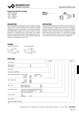
Proportional throttle valve
SEALING MATERIAL STANDARDS Proportional throttle cartridge
NBR or FKM (Viton) as standard, choice in the type code Cartridge cavity ISO 7789 ◆ direct operated M33 x 2
CANopen DRP 303-1 ◆ Q = 65 l/min ISO 7789
max
Profibus DP IEC 947-5-2 ◆ Q N max = 63 l/min
◆ p = 350 bar
Protection class EN 60 529 max
Contamination ISO 4406
efficiency
DESCRIPTION APPLICATION
Direct operated proportional throttle valve in screw-in cartridge Proportional throttle valves are suitable for smooth control of mo -
SURFACE TREATMENT INSTALLATION NOTES construction for cavity according to ISO 7789. With the solenoid vements in stationary or mobile systems. The screw-in cartridge is
◆ The cartridge body is gas-nitro-carburised Mounting type Screw-in cartridge M22 x 1,5 deenergised, the control spool is held in the closed position (DN) or perfectly suitable for installation in control blocks and is installed in
◆ The slip-on coil is zinc- / nickel-coated Mounting position Any, preferably horizontal open position (DO) by a spring. The change of the electric current is sandwich- (vertical stacked systems) and in flange plates (corres-
◆ The electronics housing / chassis is made of aluminium followed by a proportional volume flow change. Very sensitive ponding data sheets in this register). For machining the cartridge
Tightening torque M = 60 Nm Screw-in cartridge
D
M = 5 Nm knurled nut opening and closing characteristics and low hysteresis are charac- cavity in steel and aluminum blocks, cavity tools are available (hire
D
teristics of these valves. For the control, Wandfluh proportional or purchase). Please refer to the data sheets in register 2.13.
amplifiers are available (see register 1.13).
COMMISSIONING ACCESSORIES
For DSV amplifiers as a rule no parameter adjustments by the cusot- Parameterisation software See start-up
mer are required. The plugs have to be connected in accordance with Parameterisation cable for interface Article no. 219.2896
the chapter «Electrical connection». SYMBOL
USB „normally closed” DN „normally open” DO
(from plug type A on Mini B, 3 m)
Controllers are supplied configured as amplifiers. The adjustment of 2 2
the mode of control and of the controller are carried out by the custo- Mating connector (plug female) for analog interface
mer by means of the software adjustment (USB interface, Mini B). straight, soldering contact M23, 12 pole Article no. 219.2330
Further information can be found on: «www.wandfluh.com». straight, soldering contact, 7 pole Article no. 219.2335
Free- of charge download of the «PASO» software and the operation angled, soldering contact M23, 12 pole Article no. 219.2331 1 1
instructions for «DSV» hydraulic valves as well as the operation inst-
ructions CANopen Protocol resp. Profibus DP Protocol, with Device
Profile DSP-408 for «DSV». Flange body / sandwich plate NG4-Mini Data sheet 2.6-720 TYPE CODE
Flange body / sandwich plate NG6 Data sheet 2.6-740 D P PM33 - - / - HB4,5 #
Threaded body Data sheet 2.9-205 Throttle valve
Note! The mating connectors and the parameterisation cable Technical explanations Data sheet 1.0-100 Normally closed N
are not part of the delivery. Refer to chapter «Accesso- Normally open O
ries». Filtration Data sheet 1.0-50
Proportional
Attention! Auxiliary conditions for the cable: Screw-in cartridge M33 x 2
– External diameter 12 pol: 3,5…14,7 mm
– External diameter 7 pol: 8…10 mm Nominal volume flow rate Q normally closed normally open
– Wire cross section max. 1 mm 2 N 32 l/min 32 40 l/min 40
– Recommended wire cross section: 63 l/min 63
0…25 m = 0,75 mm (AWG18)
2
25…50 m = 1 mm (AWG17) Nominal voltage U N 12 VDC G12
2
24 VDC G24
without coil X5
Slip-on coil Metal housing round W
Metal housing square M
Connection execution Connector socket EN 175301-803 / ISO 4400 D
Connector socket AMP Junior-Timer J
Connector Deutsch DT04-2P G
Sealing material NBR
FKM (Viton) D1
Manual override
Design index (subject to change)
Wandfluh AG Postfach CH-3714 Frutigen 2.6-551
Tel. +41 33 672 72 72 Fax +41 33 672 72 12 sales@wandfluh.com
www.wandfluh.com Illustrations are not binding Data subject to change 6/6 Edition: 22 46 2.6-541 E www.wandfluh.com Illustrations are not binding Data subject to change 1/4 Edition: 20 21 2.6-551 E
Page 1223