
Page 1221 - Softbound_Edition_19_en
P. 1221
Proportional throttle valve
Proportional throttle valve
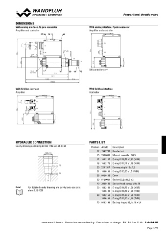
DIMENSIONS
With analog interface, 12 pole connector With analog interface, 7 pole connector
Amplifier and controller Amplifier and controller
25,30 20,21 40
X2
X2
X1
X1
s30 118.4 X4
100.4 15 X4 M22x1.5
MD=5.5Nm
(2)
35 (1) 35
X4 (controller only)
12 17 18 50 60 70
MD=5Nm 91.3
107.9
148.3 37.5
185.8
With fieldbus interface With fieldbus interface
Amplifier Controller
X2 X2
X1 X1
100.4 X3 X3
118.4 X4
35
35
HYDRAULIC CONNECTION PARTS LIST
Cavity drawing according to ISO 7789–22–01–0–98 Position Article Description
12 154.2700 Knurled nut
M22x1.5
15 253.8000 Manual override HB4,5
17 160.2187 O-ring ID 18,72 x 2,62 (NBR)
18 160.2170 O-ring ID 17,17 x 1,78 (NBR)
(2)
20 223.1317 Dummy plug M16 x 1,5
21 160.6131 O-ring ID 13,00 x 1,5 (FKM)
(1)
25 062.0102 Cover
30 072.0021 Gasket 33,2 x 59,9 x 2
(1)
40 208.0100 Socket head screw M4 x 10
Note! For detailed cavity drawing and cavity tools see data 50 160.2188 O-ring ID 18,77 x 1,78 (NBR)
sheet 2.13-1008 160.6188 O-ring ID 18,77 x 1,78 (FKM)
60 160.2156 O-ring ID 15,60 x 1,78 (NBR)
160.6156 O-ring ID 15,60 x 1,78 (FKM)
70 049.3196 Backup ring rd 16,1 x 19 x 1,4
www.wandfluh.com Illustrations are not binding Data subject to change 5/6 Edition: 22 46 2.6-541 E
Page 1221