
Page 1216 - Softbound_Edition_19_en
P. 1216
Proportional throttle valve Proportional throttle valve
Proportional throttle valve
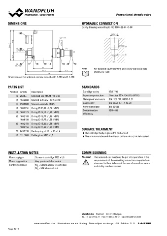
DIMENSIONS HYDRAULIC CONNECTION Proportional throttle cartridge with integrated
Cavity drawing according to ISO 7789–22–01–0–98 electronics M22 x 1,5
◆ direct operated ISO 7789
110 M22x1.5 ◆ Q = 32 l/min
max
s30 ◆ Q N max = 25 l/min
70.8 M22x1.5 ◆ p max = 350 bar
93.3 (2)
15 (2)
MD=5.5Nm
(1)
(1)
22.5 DESCRIPTION APPLICATION
(1) Direct operated proportional throttle valve with integrated electro- Proportional throttle valves with integrated electronics are per-
12 17 18 10 18 50 60 70
MD=9Nm nics as screw-in cartridge for cavity according to ISO 7789. With fectly suitable for demanding applications in which the volume flow
60 Note! For detailed cavity drawing and cavity tools see data the solenoid deenergised, the control spool is held in the closed frequently has to be changed. They are used in applications where
101.6 37.5 sheet 2.13-1008 position (DN) or open position (DO) by a spring. The change of the high valve-to-valve reproducibility, easy installation, comfortable
146 electric current is followed by a proportional volume flow change. operation and high precision are very important. The integrated
Dimensions of the solenoid coil see data sheet 1.1-183 and 1.1-184
Progressive increase and decrease of volume flow and reduced controller reliefs the machine control and operates the volume flow
hysteresis are characteristics of this valve. The Plug & Play valves control in a closed loop circuit. The applications are in the indust-
are factory set and adjusted and have therefore a high valve-to- rial as well as in the mobile hydraulics for the smooth control of
PARTS LIST STANDARDS valve reproducibility. The control takes place via an analogue inter- hydraulic actuations. The screw-in cartridge is perfectly suitable
Position Article Description Cartridge cavity ISO 7789 face or a fieldbus interface (CANopen, J1939 or Profibus DP). The for installation in control blocks and is installed in sandwich-
10 263.6... Solenoid coil MK.45 / 18 x 60 Explosion protection Directive 2014 / 34 / EU (ATEX) parameterisation takes place by means of the free of cost parame- (vertical stacked systems) and in flange plates (corresponding data
12 154.2603 Knurled nut Ex M18 x 1,5 x 18 Flameproof enclosure EN / IEC / UL 60079-1, 31 terisation and diagnostics software «PASO» or via fieldbus inter- sheets in this register). For machining the cartridge cavity in steel
and aluminum blocks, cavity tools are available (hire or purchase).
face. The USB parameterisation interface is accessible through a
15 253.8000 Manual override HB4,5 Cable entry EN 60079-0, 1, 7, 15, 31 screw plug. As an option, these valves are available with integrated Please refer to the data sheets in register 2.13.
Protection class EN 60 529
17 160.2251 O-ring ID 25,07 x 2,62 (NBR) controller. As feedback value generators sensors with voltage or
18 160.2170 O-ring ID 17,17 x 1,78 (NBR) Contamination ISO 4406 current output can be connected directly. The available controller Note! „PASO” is a Windows programm in the flow diagram
efficiency
50 160.2188 O-ring ID 18,77 x 1,78 (NBR) structures are optimised for applications with hydraulic actua- style, which enables the intuitive adjustment and storing
160.6188 O-ring ID 18,77 x 1,78 (FKM) tions. of all variable parameters. The data remain saved in
case of a power failure and can also be reproduced and
60 160.2156 O-ring ID 15,60 x 1,78 (NBR) transferred to other DSV.
160.6156 O-ring ID 15,60 x 1,78 (FKM)
70 049.3196 Backup ring rd 16,1 x 19 x 1,4 SURFACE TREATMENT
◆ The cartridge body is gas-nitro-carburised
110 111.1080 Cable gland M20 x 1,5
◆ The armature tube and the slip-on coil are zinc- / nickel-coated
SYMBOL ACTUATION
„normally closed” DN „normally open” DO Actuation Proportional solenoid, wet pin push
2 2 type, pressure tight
Connection Via device receptacle
INSTALLATION NOTES COMMISSIONING
Mounting type Screw-in cartridge M22 x 1,5 Attention! The solenoid coil must only be put into operation, if the 1 1
Mounting position Any, preferably horizontal requirements of the operating instructions supplied are
Tightening torque M = 50 Nm Screw-in cartridge observed to their full extent. In case of non-observance,
no liability can be assumed.
D
M = 5 Nm knurled nut
D
MANUAL OVERRIDE ELECTRICAL SPECIFICATIONS
HB4,5 as standard Protection class IP67 with suitable mating connector and
closed housing cover
Ramps Adjustable
Parameterisation Via fieldbus or USB
Supply voltage 12 VDC, 24 VDC
Note! Exact electrical specifications and detailed description
of «DSV» electronics can be found on data sheet
1.13-76.
Wandfluh AG Postfach CH-3714 Frutigen
Tel. +41 33 672 72 72 Fax +41 33 672 72 12 sales@wandfluh.com
www.wandfluh.com Illustrations are not binding Data subject to change 4/4 Edition: 21 21 2.6-535 E www.wandfluh.com Illustrations are not binding Data subject to change 1/6 Edition: 22 46 2.6-541 E
Page 1216