Page 1329 - Softbound_Edition_19_en
P. 1329

A
                                                                               A
                                                                                               B
                                                                                       PT
                                                      PT
              A
                                                              B
                             B
                     PT
                                               A
                                                              B
                                               A
                     PT
                                                      PT
              A      PT      B                 A      PT      B                A       PT      B
                             B
                                                                                       PT
                                                                                               B
                                                                               A
                                                                                     Proportional flow control valve
 Proportional flow control valves                                                   Proportional flow control valves
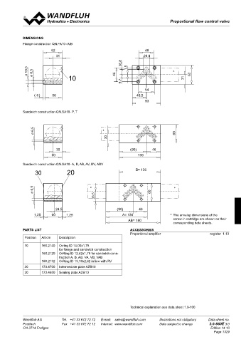
 SCREw-IN CARTRIDGES INSTALLED  DIMENSIONS
 The following screw-in cartridges are used in either the flange body or the sandwich body:
            Flange construction QN.FA10 - A/B
 Type   Designation   Data sheet no.   Qmax*  62                         48
 QNPPM33   normally closed    2.6-651   80 l/min
 QNPPM33-./ME  normally closed, with integrated electronics   2.6-659   63 l/min  31  20,8
    *  Can deviate from the values on the data sheets of the screw-in cartridges.  16,8
    **  Do not use anymore for new applications.                1,5
              10,5  6,5                                                               ∗
              Ø  Ø                                        46                                   62
                                   10                                                       31
                                                             9,7
                                                                         54
 TYPE CHARTS      (  6)    56                                        46,5
 Meter-out flow control  Meter-in flow control                           93
            Sandwich construction QN.SA10 - P, T
 QN.FA10-A/B  QN.SA10-A  QN.SA10-AV
 A  PT  B  A  PT  B  A  PT  B  6,5                  ∗
                  Ø                                                                     60
                                                      30
 QN.SA10-P  QN.SA10-B  QN.SA10-BV
                             30                                  ( 90)      46
 A  PT  B  A  PT  B  A  PT  B  60                                    136

            Sandwich construction QN.SA10 - A, B, AB, AV, BV, ABV
 QN.SA10-T  QN.SA10-AB  QN.SA10-ABV                                 B= 136
                  30              20

 A  PT  B  A  PT  B  A  PT  B
                 6,5                          ∗                                        ∗
                 Ø                                                         60
                                                33,5
 By  turning  around  valves  with  meter-out  function,  meter-in  function
 can be achieved:           24,5                           ( 90)      46
 A   turns into BV  1,25   60     1,25                       A= 136                  *   The envelop dimensions of the
 62
 B   turns into AV  48                                                                 screw-in cartridge are shown on their
 AB   turns into ABV  20,8                                      AB= 180                corresponding data sheets.
 31
 Valves for flow control are supplied respectively with a sealing plate
 and an intermediate plate.  16,8  PARTS LIST                    ACCESSORIES
 10,5  6,5  1,5  ∗  Position  Article  Description               Proportional amplifier                  register  1.13
 Ø  Ø  46  62
 REMARK!  10  31  10  160.2140  O-ring ID 14,00x1,78
 9,7
 Detailed performance data and additional hydraulic and   for flange and sandwich construction
 electric specifications may by drawn from the data sheets   160.2120  O-Ring ID 12,42x1,78 for sandwich cons-
 of the corresponding installed screw-in cartridge.  54  truction A, B, AB, VA, VB, VAB
 (  6)  56  46,5      160.2132  O-Ring ID 13,10x2,62 in line with RV
 93          20       173.4700  Intermediate plate AZB10
 CAUTION!
 The performace  data, especially the  „pressure-flow-  30  173.4650  Sealing plate ADB10
 characteristic„ on the data sheets of the screw-in ca-
 tridges, refer to the screw-in cartridges only. The additional
 pressure drop of the flange body, resp. sandwich body
 must be taken into consideration.
 6,5  ∗
 Ø  60
 30
                                                                 Technical explanation see data sheet 1.0-100
 30  ( 90)  46
 Wandfluh AG   60  Tel.  +41 33 672 72 72   E-mail:  sales@wandfluh.com   Illustrations not obligatory   Data sheet no.  Wandfluh AG   Tel.  +41 33 672 72 72   E-mail:  sales@wandfluh.com   Illustrations not obligatory   Data sheet no.
 136
 Postfach   Fax  +41 33 672 72 12   Internet:  www.wandfluh.com   Data subject to change   2.6-860E 2/3  Postfach   Fax  +41 33 672 72 12   Internet:  www.wandfluh.com   Data subject to change   2.6-860E 3/3
 CH-3714 Frutigen                   Edition 14 10  CH-3714 Frutigen                                      Edition 14 10
                                                                                                           Page 1329
 30  20  B= 136


 6,5  ∗  ∗
 Ø  60
 33,5

 24,5  ( 90)  46
 1,25  60  1,25  A= 136
 AB= 180
   1324   1325   1326   1327   1328   1329   1330   1331   1332   1333   1334