
Page 1327 - Softbound_Edition_19_en
P. 1327
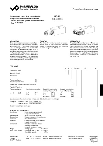
Proportional flow control valve
 Proportional flow control valves                                                   Proportional flow control valves


 SCREW-IN CARTRIDGES INSTALLED  TYPE CHARTS  Proportional 2-way flow control valve  NG10
 The following screw-in cartridges are used in either the flange body or   Flange- and sandwich construction
 the sandwich body:  QD.FA06-A/B  QD.SA06-P                  ISO 4401-05
            •  Direct operated,  pressure compensated
 Typ      Bezeichnung   Datenblatt Nr.  Qmax*  •  p max   = 350 bar
 QDPPM22   3-way-construction    2.6-644   40 l/min
 QDPPM22-../ME  3-way-construction,
        with integrated electronics  2.6-647   40 l/min
 QDBPM22   3-way-construction,    A  PT  B  A  PT  B
        Explosion protection   2.6-648   40 l/min

    *  Can deviate from the values on the data sheets of the screw-in cartridges.


 REMARK!  REMARK!  DESCRIPTION                 FUNCTION                           APPLICATION
 Detailed performance data and additional hydraulic and   Detailed performance data and additional hydraulic and   Direct operated, pressure compensated pro-  The 2-way flow control valve with series con-  Proportional flow control valves in flange- and
 PT
 A  electric specifications may by drawn from the data sheets   electric specifications may by drawn from the data sheets   portional flow control valve in flange- and sand-  nected pressure balance (primary controller)   sandwich construction are suitable for precice
 PT
 B
 B
 A
 of the corresponding installed screw-in cartridge.  of the corresponding installed screw-in cartridge.  wich  construction.  Proportional  flow  control   serves to maintain the speed of a consumer   feed control systems, where the supply flow
            screw-in cartridges M33x2 acc. to ISO 7789   constant independent of the load.  has to be maintained constant with a changing
            are installed. In the sandwich plates for A, B                        load. used where the supply volume flow has to
            and AB line, a bypass check valve for reversed                        be kept constant even when the load fluctuates.
 45  21,5  19  free flow is installed. A  bypass non-return valve                 Depending on the application, a distinction is
 25  17,8   plate for the flange valve, for free flow from B to                   made between controlling the forward flow or
 10         A, can be ordered separately. Two flow ranges                         the return flow.
            are available. The flange body is painted and
            the sandwich plates are phosphatized.
        ∗
 DIMENSIONS
 9,5  5,5  45  31  21  32,5
 Flange construction QD.FA06-A/B  Ø  Ø  TYPE CODE
 45  21,5  19                                                               Q  N   P      A10 -   -            #
 25  17,8   Flow control valve
 10  4 ( )  41  32  88  Normally closed
            Proporional
 ∗
 9,5  45  31  21  32,5  Flange construction       F
 Ø  5,5  ∗
            Sandwich construction         S
 Ø
 5,5     45  International standard interface ISO, NG10
 Ø
 4 ( )  41  32  Type list / Function:
 88         Flange construction   Sandwich construction   Sandwich construction   Sandwich construction
 18,5  85  32                                      meter-out flow control   meter-in flow control
 Sandwich construction QDPSA06-P
 40         A → B      A/B      in P      P        in A        A      in A              AV
                                in T      T        in  B       B      in B              BV
 ∗                                                 in A and B   AB    in A and B         ABV
 5,5  45    Nominal volume flow level, nominal voltage, etc. of the built-in screw-in cartridge
 Ø          Examples:    QNPFA10 - A/B -  32 - G24/WD - D1
 *  The envelop dimensions of the screw-in       QNPSA10 - A -   63 - G12/ME - A1
   cartridge are shown on their
 18,5  85  32    corresponding data sheets.  Design-Index (Subject to change)
 40
            GENERAL SPECIFICATIONS
            Description      Direct operated proportional
                             2-way flow control valve
            Nominal size     NG10 acc. to ISO 4401-05
 PARTS LIST  ACCESSORIES  Construction   Flange- and sandwich construction
 Proportional amplifier   register 1.13  Operation   Proportional solenoid
 Position  Article  Description  Mounting   4 holes for socket cap screws  M6
                             or studs screws M6
 10  160.2093  O-ring ID 9,25x1,78  Connection   Threaded connection plates
                             Multi-flange subplates
                             Longitudinal stacking system
            Weight           • Flange type       m = 2,20 kg
            (without screw-in cartridge)   • Sandwich type P,T,A,B   m = 3,10 kg
 Technical explanation see data sheet 1.0-100      • Sandwich type AB   m = 3,75 kg


 Wandfluh AG   Tel.  +41 33 672 72 72   E-mail:  sales@wandfluh.com   Illustrations not obligatory   Data sheet no.  Wandfluh AG   Tel.  +41 33 672 72 72   E-mail:  sales@wandfluh.com   Illustrations not obligatory   Data sheet no.
 Postfach   Fax  +41 33 672 72 12   Internet:  www.wandfluh.com   Data subject to change   2.6-842E 2/2  Postfach   Fax  +41 33 672 72 12   Internet:  www.wandfluh.com   Data subject to change   2.6-860E 1/3
 CH-3714 Frutigen     Edition 17 32  CH-3714 Frutigen                                                    Edition 14 10
                                                                                                           Page 1327