
Page 1251 - Softbound_Edition_19_en
P. 1251
Proportional flow control valve
Proportional flow control valve
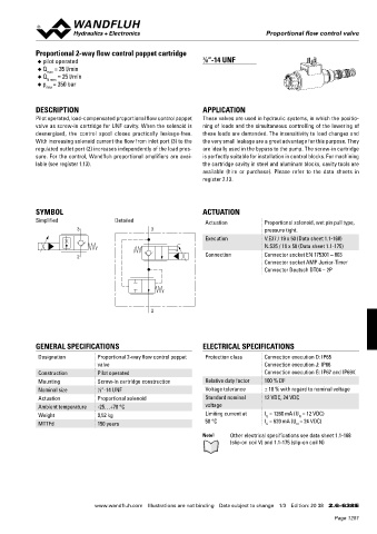
Proportional 2-way flow control poppet cartridge
◆ pilot operated 7 ⁄8 “-14 UNF
◆ Q = 35 l/min
max
◆ Q N max = 25 l/min
◆ p = 350 bar
max
DESCRIPTION APPLICATION
Pilot operated, load-compensated proportional flow control poppet These valves are used in hydraulic systems, in which the positio-
valve as screw-in cartridge for UNF cavity. When the solenoid is ning of loads and the simultaneous controlling of the lowering of
deenergised, the control spool closes practically leakage-free. these loads are demanded. The insensitivity to load changes and
With increasing solenoid current the flow from inlet port (3) to the the very small leakage are a great advantage for this purpose. They
regulated outlet port (2) increases independently of the load pres- are ideally used in the bypass to the pump. The screw-in cartridge
sure. For the control, Wandfluh proportional amplifiers are avai- is perfectly suitable for installation in control blocks. For machining
lable (see register 1.13). the cartridge cavity in steel and aluminum blocks, cavity tools are
available (hire or purchase). Please refer to the data sheets in
register 2.13.
SYMBOL ACTUATION
Simplified Detailed Actuation Proportional solenoid, wet pin pull type,
3 3 pressure tight.
Execution V.E37 / 19 x 50 (Data sheet 1.1-168)
N.S35 / 19 x 50 (Data sheet 1.1-175)
2 Connection Connector socket EN 175301 – 803
Connector socket AMP Junior-Timer
Connector Deutsch DT04 – 2P
2
GENERAL SPECIFICATIONS ELECTRICAL SPECIFICATIONS
Designation Proportional 2-way flow control poppet Protection class Connection execution D: IP65
valve Connection execution J: IP66
Construction Pilot operated Connection execution G: IP67 and IP69K
Mounting Screw-in cartridge construction Relative duty factor 100 % DF
Nominal size 7 ⁄8 “-14 UNF Voltage tolerance ± 10 % with regard to nominal voltage
Actuation Proportional solenoid Standard nominal 12 VDC, 24 VDC
Ambient temperature -25…+70 °C voltage
Weight 0,52 kg Limiting current at I = 1260 mA (U = 12 VDC)
G
N
MTTFd 150 years 50 °C I = 620 mA (U = 24 VDC)
G
N
Note! Other electrical specifications see data sheet 1.1-168
(slip-on coil V) and 1.1-175 (slip-on coil N)
www.wandfluh.com Illustrations are not binding Data subject to change 1/3 Edition: 20 38 2.6-638 E
Page 1251