Page 1250 - Softbound_Edition_19_en
P. 1250

Proportional flow control valve                                                                                              Proportional flow control valve
                                                                               Proportional flow control valve


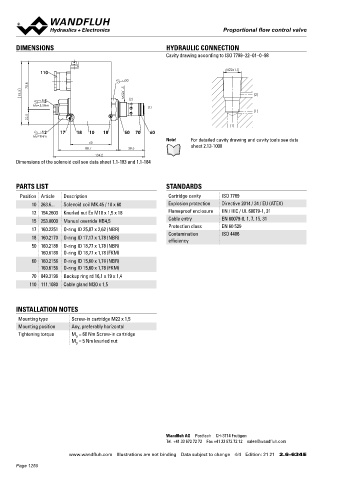
       DIMENSIONS                                          HYDRAULIC CONNECTION                                                    Proportional 2-way flow control poppet cartridge
                                                           Cavity drawing according to ISO 7789–22–01–0–98                          ◆  pilot operated                                   7 ⁄8 “-14 UNF
                                                                                                                                    ◆  Q  = 35 l/min
                                                                                                                                       max
               110                                                               M22x1.5                                            ◆  Q N max  = 25 l/min
                                                                                                                                    ◆  p max  = 350 bar
                                            s30
            70.8
         93.3                                 M22x1.5                                     (2)
                15                            (2)                                                                                  DESCRIPTION                                          APPLICATION
             MD=5.5Nm                                (1)                                                                           Pilot operated, load-compensated proportional flow control poppet   These valves are used in hydraulic systems, in which the positio-
                                                                                          (1)                                      valve as screw-in cartridge for UNF cavity. When the solenoid is   ning of loads and the simultaneous controlling of the lowering of
            22.5                                                                                                                   deenergised,  the  control  spool  closes  practically  leakage-free.   these loads are demanded. The insensitivity to load changes and
                                                                                  (1)                                              With increasing solenoid current the flow from inlet port (3) to the   the very small leakage are a great advantage for this purpose. They
                12    17    18  10   18      50  70   60                                                                           regulated outlet port (2) increases independently of the load pres-  are ideally used in the bypass to the pump. The screw-in cartridge
             MD=9Nm                                                 For detailed cavity drawing and cavity tools see data
                                 60                        Note!                                                                   sure. For the control, Wandfluh proportional amplifiers are avai-  is perfectly suitable for installation in control blocks. For machining

                                88.7           38.6                 sheet 2.13-1008                                                lable (see register 1.13).                           the cartridge cavity in steel and aluminum blocks, cavity tools are
                                   134.2                                                                                                                                                available  (hire  or  purchase).  Please  refer  to  the  data  sheets  in
       Dimensions of the solenoid coil see data sheet 1.1-183 and 1.1-184                                                                                                                 register 2.13.


       PARTS LIST                                          STANDARDS
                                                                                                                                   SYMBOL                                               ACTUATION
        Position Article  Description                       Cartridge cavity   ISO 7789                                            Simplified                Detailed                    Actuation          Proportional solenoid, wet pin pull type,
            10 263.6...  Solenoid coil MK.45 / 18 x 60      Explosion protection  Directive 2014 / 34 / EU (ATEX)                               3                       3                                   pressure tight.
            12 154.2603  Knurled nut Ex M18 x 1,5 x 18      Flameproof enclosure  EN / IEC / UL 60079-1, 31                                                                              Execution          V.E37 / 19 x 50 (Data sheet 1.1-168)
            15 253.8000  Manual override HB4,5              Cable entry        EN 60079-0, 1, 7, 15, 31                                                                                                     N.S35 / 19 x 50 (Data sheet 1.1-175)
            17 160.2251  O-ring ID 25,07 x 2,62 (NBR)       Protection class   EN 60 529                                                        2                                        Connection         Connector socket EN 175301 – 803
                                                            Contamination      ISO 4406
            18 160.2170  O-ring ID 17,17 x 1,78 (NBR)       efficiency                                                                                                                                      Connector socket AMP Junior-Timer
            50 160.2188  O-ring ID 18,77 x 1,78 (NBR)                                                                                                                                                       Connector Deutsch DT04 – 2P
               160.6188  O-ring ID 18,77 x 1,78 (FKM)
            60 160.2156  O-ring ID 15,60 x 1,78 (NBR)
               160.6156  O-ring ID 15,60 x 1,78 (FKM)
            70 049.3196  Backup ring rd 16,1 x 19 x 1,4
                                                                                                                                                                        2
           110 111.1080  Cable gland M20 x 1,5


       INSTALLATION NOTES                                                                                                          GENERAL SPECIFICATIONS                               ELECTRICAL SPECIFICATIONS
       Mounting type      Screw-in cartridge M22 x 1,5                                                                              Designation        Proportional 2-way flow control poppet   Protection class  Connection execution D: IP65
       Mounting position  Any, preferably horizontal                                                                                                   valve                                                Connection execution J: IP66
       Tightening torque  M  = 60 Nm Screw-in cartridge                                                                             Construction       Pilot operated                                       Connection execution G: IP67 and IP69K
                            D
                          M  = 5 Nm knurled nut                                                                                                                                          Relative duty factor  100 % DF
                            D                                                                                                       Mounting           Screw-in cartridge construction
                                                                                                                                    Nominal size       7 ⁄8 “-14 UNF                     Voltage tolerance  ± 10 % with regard to nominal voltage
                                                                                                                                    Actuation          Proportional solenoid             Standard nominal   12 VDC, 24 VDC
                                                                                                                                    Ambient temperature  -25…+70 °C                      voltage
                                                                                                                                    Weight             0,52 kg                           Limiting current at  I  = 1260 mA (U  = 12 VDC)
                                                                                                                                                                                                                      N
                                                                                                                                                                                                            G
                                                                                                                                    MTTFd              150 years                         50 °C              I  = 620 mA (U  = 24 VDC)
                                                                                                                                                                                                            G
                                                                                                                                                                                                                      N
                                                                                                                                                                                        Note!    Other electrical specifications see data sheet 1.1-168
                                                                                                                                                                                                 (slip-on coil V) and 1.1-175 (slip-on coil N)


                                                           Wandfluh AG  Postfach  CH-3714 Frutigen
                                                           Tel. +41 33 672 72 72  Fax +41 33 672 72 12  sales@wandfluh.com

                         www.wandfluh.com  Illustrations are not binding  Data subject to change  4/4  Edition: 21 21  2.6-634 E                      www.wandfluh.com  Illustrations are not binding  Data subject to change  1/3  Edition: 20 38  2.6-638 E
       Page 1250
   1245   1246   1247   1248   1249   1250   1251   1252   1253   1254   1255