
Page 1319 - Softbound_Edition_19_en
P. 1319
A
B
PT
PT
A
A
B
A
B
PT
PT
B
A
PT
B
B
PT
A
A PT B A PT B A PT B
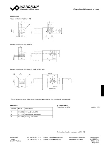
Proportional flow control valve
Proportional flow control valves Proportional flow control valves
SCREW-IN CARTRIDGES INSTALLED DIMENSIONS
The following screw-in cartridges are used in either the flange body or the sandwich body:
Flange construction QN.FA04 - A/B
Type Designation Data sheet no. Qmax* 38 28
QNPPM22 normally closed 2.6-631 25 l/min
QNPPM22-../ME normally closed, with integrated electronics 2.6-633 25 l/min 19 10 14
QNBPM22 normally closed, explosion proof Exd 2.6-634 25 l/min
P
* Can deviate from the values on the data sheets of the screw-in cartridges.
Ø 9.5 Ø 5.5 19 ∗ T A B To 14 27 38
(5.5) 32.5 49 (27)
TYPE CHARTS 76
Meter-out flow control Meter-in flow control
Sandwich construction QN.SA04 - P, T
20
QN.FA04-A/B QN.SA04-A QN.SA04-AV P
A B 40
A PT B A PT B A PT B ∗ T To
Ø 5.5 40 T=19 / P=21 63 (27)
QN.SA04-P QN.SA04-B QN.SA04-BV 90
A PT B A PT B A PT B
Sandwich construction QN.SA04 - A, B, AB, AV, BV, ABV
QN.SA04-T QN.SA04-AB QN.SA04-ABV 30 20 A,AV=90
20
(63) 27
A PT B A PT B A PT B P
Ø 5.5 ∗ T A B To 40 ∗
20
1.5 40 1.5 B,BV=90
By turning around valves with meter-out function, meter-in function AB,ABV=126
can be achieved:
A turns into BV
B turns into AV 38 28
AB turns into ABV 19 14
10
Valves for flow control are supplied respectively with a sealing plate
and an intermediate plate. * The envelop dimensions of the screw-in cartridge are shown on their corresponding data sheets.
P
Ø 9.5 Ø 5.5 ∗ T A B To 14 27 38
REMARK! 19 PARTS LIST ACCESSORIES
Detailed performance data and additional hydraulic and (27) Proportional amplifier register 1.13
32.5
49
(5.5)
electric specifications may by drawn from the data sheets Position Article Description
of the corresponding installed screw-in cartridge. 76
10 160.2052 O-ring ID 5,28x1,78
20 173.1700 Intermediate plate BZB4
CAUTION!
The performace data, especially the „pressure-flow-cha- 30 173.1650 Sealing plate BDB4
racteristic„ on the data sheets of the screw-in catridges,
20
refer to the screw-in cartridges only. The additional pres-
sure drop of the flange body, resp. sandwich body must
be taken into consideration. P
A B 40
∗ T To
Ø 5.5 40 T=19 / P=21 63 90 (27) Technical explanation see data sheet 1.0-100
Wandfluh AG Tel. +41 33 672 72 72 E-mail: sales@wandfluh.com Illustrations not obligatory Data sheet no. Wandfluh AG Tel. +41 33 672 72 72 E-mail: sales@wandfluh.com Illustrations not obligatory Data sheet no.
Postfach Fax +41 33 672 72 12 Internet: www.wandfluh.com Data subject to change 2.6-820E 2/3 Postfach Fax +41 33 672 72 12 Internet: www.wandfluh.com Data subject to change 2.6-820E 3/3
CH-3714 Frutigen Edition 16 06 CH-3714 Frutigen Edition 16 06
Page 1319
30 20 20 A,AV=90
(63) 27
P
∗ ∗
Ø 5.5 T A B To 40
20
1.5 40 1.5 B,BV=90
AB,ABV=126