
Page 1340 - Softbound_Edition_19_en
P. 1340
Non-return valve Non-return valve
Check valve
PERFORMANCE SPECIFICATIONS Non-return valve hydraulically pilot operated
Oil viscosity u = 30 mm /s M33 x 2
2
Screw-in cartridge construction ISO 7789
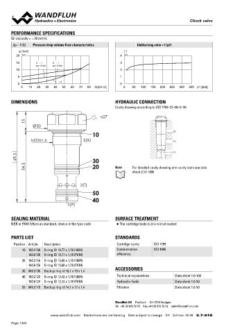
∆p = f (Q) Pressure drop volume flow characteristics Unblocking ratio = f (p1) ◆ Q = 150 l/min
max
p [bar] [-] ◆ p = 350 bar
max
20 K0300 4 K0286
15 2 → 1 2 → 1 3
pa= 2 bar pa= 5 bar DESCRIPTION APPLICATION
10 2 Hydraulically pilot operated non-return valve in screw-in cartridge Pilot operated non-return valves are used for closing off pressuri-
construction for cavity according to ISO 7789. In the free flow sed hydraulic cylinders leak free, for example in lifting or clamping
5 1
direction (2 → 1), the volume flow opens the spring loaded seat devices. The spool valve that directs the volume flow to port x,
0 1 → 2 0 cone. In the opposite direction (1 → 2), the spring keeps the valve should have both service ports connected to the tank in the rest
0 10 20 30 40 50 60 70 80 Q [l/min] 0 50 100 150 200 250 300 350 p1 [bar]
closed. If pressure is built up in connection x, the pilot control spool position for reasons of operational safety.
is shifted and the non-return valve of the closed off port is opened
by this. The required pilot control pressure depends on the pilot
DIMENSIONS HYDRAULIC CONNECTION ratio.
Cavity drawing according to ISO 7789–22–06–0–98
SYMBOL INSTALLATION NOTES
s27 M22x1.5
15 Mounting type Screw-in cartridge M33 x 2
Ø30 1 Mounting position Any
Tightening torque M = 80 Nm screw-in cartridge
(3)
10 D
M22x1.5 3(X) (2)
2 x (3)
(1)
69.5 30 (1) TYPE CODE
54.5 20 Note! For detailed cavity drawing and cavity tools see data Non-return valve hydraulically pilot operated RNX PM33 - - #
sheet 2.13-1006
Screw-in cartridge M33 x 2
2(T) Opening pressure p a 2 bar 2
5 bar 5
50 Sealing material NBR
40 FKM (Viton) D1
1(P) NBR 872 Z604
Design index (subject to change)
SEALING MATERIAL SURFACE TREATMENT 2.7-62
NBR or FKM (Viton) as standard, choice in the type code ◆ The cartridge body is zinc-nickel coated GENERAL SPECIFICATIONS HYDRAULIC SPECIFICATIONS
Designation Non-return valve hydraulically pilot Working pressure p = 350 bar
max
PARTS LIST STANDARDS operated Opening pressure p = 2; 5 bar
a
Mounting Screw-in cartridge construction Maximum volume flow Q = 150 l/min
Position Article Description Cartridge cavity ISO 7789 Nominal size M33 x 2 according to ISO 7789 Leakage oil Seat tight, max. 0,15 ml / min (approx. 3
max
10 160.2188 O-ring ID 18,77 x 1,78 (NBR) Contamination ISO 4406 Actuation None drops / min) at 30 cSt
160.6188 O-ring ID 18,77 x 1,78 (FKM) efficiency
Ambient temperature -25…+90 °C Fluid Mineral oil, other fluid on request
20 160.2156 O-ring ID 15,60 x 1,78 (NBR) Weight 0,37 kg Viscosity range 12 mm /s…320 mm /s
2
2
160.6156 O-ring ID 15,60 x 1,78 (FKM) Temperature range -25…+90 °C (NBR)
30 049.3196 Backup ring rd 16,1 x 19 x 1,4 ACCESSORIES fluid -20…+90 °C (FKM)
40 160.2120 O-ring ID 12,42 x 1,78 (NBR) Technical explanations Data sheet 1.0-100 Contamination Class 20 / 18 / 14
160.6124 O-ring ID 12,42 x 1,78 (FKM) Hydraulic fluids Data sheet 1.0-50 efficiency
50 049.3176 Backup ring rd 14,1 x 17 x 1,4 Filtration Data sheet 1.0-50 Filtration Required filtration grade ß 10…16 ≥ 75,
see data sheet 1.0-50
Pilot ratio See characteristic
Wandfluh AG Postfach CH-3714 Frutigen Area ratio i = 1 : 3,2
Tel. +41 33 672 72 72 Fax +41 33 672 72 12 sales@wandfluh.com
www.wandfluh.com Illustrations are not binding Data subject to change 2/2 Edition: 18 44 2.7-61 E www.wandfluh.com Illustrations are not binding Data subject to change 1/2 Edition: 18 44 2.7-62 E
Page 1340