Page 1244 - Softbound_Edition_19_en
P. 1244

Proportional flow control valve                                                                                              Proportional flow control valve
                                                                               Proportional flow control valve


       PERFORMANCE SPECIFICATIONS                                                                                                  DIMENSIONS
       Oil viscosity u = 30 mm /s                                                                                                  With analog interface, 12 pole connector             With analog interface, 7 pole connector
                       2
                                                                                                                                   Amplifier and controller                             Amplifier and controller
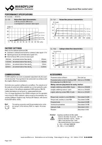
       Q = f (I)  Volume flow signal characteristics        Q = f (p)  Volume flow pressure characteristics
                  at 50 bar pressure difference /              Q [l/min]                                                                              25,30      20,21  40                               X2
                  s corresponds to command value signal       40  K0964

          Q [l/min]                                           30                                                                                                X2                                  X1
         40  K1137                                                                                  Q  = 25 l/min                                         X1
                                                                                                     N
                                                              20
         30                                                                                         Q N  = 16 l/min                                                                       118.4
                                              Q N = 25 l/min  10                                                                                                             s30                    X4
         20                                                                                         Q  = 8 l/min                      100.4               X4
                                                                                                     N
                                              Q N = 16 l/min                                        Q  = 3,2 l/min                               15
                                                               0                                     N                                       MD=5.5Nm                      M22x1.5
         10                                   Q N = 8 l/min     0    50  100  150  200  250  300  350 p [bar]                                                                (2)
                                              Q N = 3,2 l/min                                                                                                                               35
          0                                                                                                                            35                                         (1)
           0   10 20  30  40  50  60 70 80  90  100  s [%]
                                                                                                                                                                                        X4 (controller only)
                                                                                                                                                  12    17            18   50  60  70
       FACTORY SETTINGS                                     Q  = f (p)  Leakage volume flow characteristics                                    MD=5Nm           78.4
       Dither set for optimum hysteresis DN                  L      3                                                                                          95
       ◆ = Deadband: solenoid switched off at command value signal < 5 %  100 Q [cm /min]                                                                 135.4    174       38.6
                                                                 K0965
       ● = Opening pressure at command value signal 10 %
       ■ = Volume flow at 70% command value signal            80
                                                              60
       18,0 l/min  at nominal volume flow rate Q  25 l/min                                                                         With fieldbus interface                              With fieldbus interface
                                     N
       11,9 l/min  at nominal volume flow rate Q N  16 l/min  40                                                                   Amplifier                                            Controller
       6,0 l/min  at nominal volume flow rate Q   8 l/min     20                                                                                           X2                                          X2
                                     N                         0
       2,6 l/min  at nominal volume flow rate Q N  3,2 l/min     0   50   100  150  200  250  300  350 p [bar]                                      X1                                           X1
                                                                                                                                                    X3                                           X3
                                                                                                                                      100.4
       COMMISSIONING                                       ACCESSORIES                                                                                                                    118.4   X4
       For DSV amplifiers as a rule no parameter adjustments by the cusot-  Parameterisation software  See start-up
       mer are required. The plugs have to be connected in accordance with                                                               35
       the chapter «Electrical connection».                 Parameterisation cable for interface USB  Article no. 219.2896
                                                            (from plug type A on Mini B, 3 m)                                                                                               35

       Controllers are supplied configured as amplifiers. The adjustment of   Mating connector (plug female) for analog interface
       the mode of control and of the controller are carried out by the custo-  straight, soldering contact M23, 12 pole  Article no. 219.2330
       mer by means of the software adjustment (USB interface, Mini B).  straight, soldering contact, 7 pole  Article no. 219.2335
       Further information can be found on: «www.wandfluh.com».  angled, soldering contact M23, 12 pole  Article no. 219.2331
       Free- of charge download of the «PASO» software and the opera tion                                                          HYDRAULIC CONNECTION                                 PARTS LIST
       instructions for «DSV» hydraulic valves as well as the opera tion inst-                                                     Cavity drawing according to ISO 7789–22–01–0–98        Position Article  Description
       ructions CANopen Protocol resp. Profibus DP Protocol, with Device   Flange body / sandwich plate NG4-Mini  Data sheet 2.6-820                                                          12 154.2700  Knurled nut
       Profile DSP-408 for «DSV».                           Flange body / sandwich plate NG6  Data sheet 2.6-840                                         M22x1.5
                                                                                                                                                                                              15 253.8000  Manual override HB4,5
                                                            Threaded body                   Data sheet 2.9-205                                                                                17 160.2187  O-ring ID 18,72 x 2,62 (NBR)
       Note!     The mating connectors and the parameterisation cable   Technical explanations  Data sheet 1.0-100
               are not part of the delivery. Refer to chapter «Accesso-  Hydraulic fluids   Data sheet 1.0-50                                                     (2)                         18 160.2170  O-ring ID 17,17 x 1,78 (NBR)
               ries».                                                                                                                                                                         20 223.1317  Dummy plug M16 x 1,5
                                                            Filtration                      Data sheet 1.0-50                                                                                 21 160.6131  O-ring ID 13,00 x 1,5 (FKM)
                                                                                                                                                                  (1)
                                                                                                                                                                                              25 062.0102  Cover
                                                           Attention!  Auxiliary conditions for the cable:                                                                                    30 072.0021  Gasket 33,2 x 59,9 x 2
                                                                    – External diameter 12 pol: 3,5…14,7 mm                                               (1)
                                                                    – External diameter 7 pol: 8…10 mm                                                                                        40 208.0100  Socket head screw M4 x 10
                                                                    – Wire cross section max. 1 mm 2                               Note!    For detailed cavity drawing and cavity tools see data   50 160.2188  O-ring ID 18,77 x 1,78 (NBR)
                                                                    – Recommended wire cross section:                                       sheet 2.13-1008                                      160.6188  O-ring ID 18,77 x 1,78 (FKM)
                                                                    0…25 m = 0,75 mm  (AWG18)                                                                                                 60 160.2156  O-ring ID 15,60 x 1,78 (NBR)
                                                                                 2
                                                                    25…50 m = 1 mm  (AWG17)
                                                                                2
                                                                                                                                                                                                 160.6156  O-ring ID 15,60 x 1,78 (FKM)
                                                                                                                                                                                              70 049.3196  Backup ring rd 16,1 x 19 x 1,4


                         www.wandfluh.com  Illustrations are not binding  Data subject to change  4/6  Edition: 22 46  2.6-633 E                      www.wandfluh.com  Illustrations are not binding  Data subject to change  5/6  Edition: 22 46  2.6-633 E
       Page 1244
   1239   1240   1241   1242   1243   1244   1245   1246   1247   1248   1249