
Page 1234 - Softbound_Edition_19_en
P. 1234
Proportional flow control valve Proportional flow control valve
Proportional flow control valve
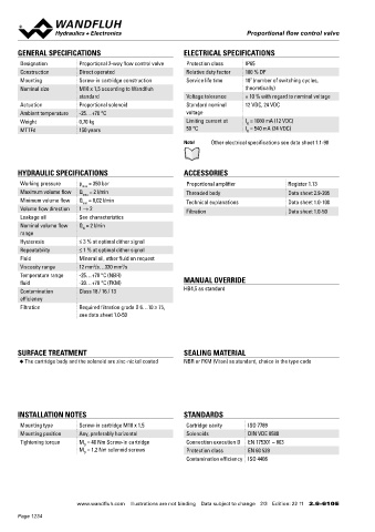
GENERAL SPECIFICATIONS ELECTRICAL SPECIFICATIONS PERFORMANCE SPECIFICATIONS
2
Designation Proportional 2-way flow control valve Protection class IP65 Oil viscosity u = 30 mm /s
Construction Direct operated Relative duty factor 100 % DF Q = f (I) Volume flow signal characteristics Q = f (p) Volume flow pressure characteristics
Mounting Screw-in cartridge construction Service life time 10 (number of switching cycles, Q [l/min] Q [l/min]
7
Nominal size M18 x 1,5 according to Wandfluh theoretically) 4 K4282 3 K4282
standard Voltage tolerance ± 10 % with regard to nominal voltage 2.5
Actuation Proportional solenoid Standard nominal 12 VDC, 24 VDC 3 2
Ambient temperature -25…+70 °C voltage 2 1.5
Weight 0,70 kg Limiting current at I = 1080 mA (12 VDC) 1
G
MTTFd 150 years 50 °C I = 540 mA (24 VDC) 1 0.5
G
0 0 p [bar]
Note! Other electrical specifications see data sheet 1.1-90 0 10 20 30 40 50 60 70 80 90 100 I [%] 0 50 100 150 200 250 300 350
Q = f (p) Leakage volume flow characteristics
L
HYDRAULIC SPECIFICATIONS ACCESSORIES Q [cm /min]
3
Working pressure p = 350 bar Proportional amplifier Register 1.13 80 K0577
max
Maximum volume flow Q = 2 l/min Threaded body Data sheet 2.9-205 60
max
Minimum volume flow Q = 0,02 l/min
min Technical explanations Data sheet 1.0-100 40
Volume flow direction 1 → 2 Filtration Data sheet 1.0-50
Leakage oil See characteristics 20
Nominal volume flow Q = 2 l/min 0
N
range 0 50 100 150 200 250 300 350 p [bar]
Hysteresis ≤ 3 % at optimal dither signal
Repeatability ≤ 1 % at optimal dither signal
Fluid Mineral oil, other fluid on request DIMENSIONS HYDRAULIC CONNECTION
Viscosity range 12 mm /s…320 mm /s Cavity drawing according to Wandfluh standard
2
2
Temperature range -25…+70 °C (NBR)
fluid -20…+70 °C (FKM) MANUAL OVERRIDE s24 M18x1,5
Contamination Class 18 / 16 / 13 HB4,5 as standard 30
efficiency 15 M18x1.5
Filtration Required filtration grade ß 6…10 ≥ 75, 68.8 MD=5.5Nm (2)
see data sheet 1.0-50 (2) (1)
29 (1) (1)
40 10 18 50 70 60 (1)
SURFACE TREATMENT SEALING MATERIAL MD= 1.2Nm 10.3 60.8 47
◆ The cartridge body and the solenoid are zinc-nickel coated NBR or FKM (Viton) as standard, choice in the type code Note! For detailed cavity drawing and cavity tools see data
118.1 sheet 2.13-1038
PARTS LIST
Position Article Description
10 256.2418 Proportional solenoid PI29V-G12
INSTALLATION NOTES STANDARDS 256.2453 Proportional solenoid PI29V-G24
15 253.8000 Manual override HB4,5
Mounting type Screw-in cartridge M18 x 1,5 Cartridge cavity ISO 7789
Mounting position Any, preferably horizontal Solenoids DIN VDE 0580 18 160.2120 O-ring ID 12,42 x 1,78 (NBR)
Tightening torque M = 40 Nm Screw-in cartridge Connection execution D EN 175301 – 803 30 219.2002 Electric plug B (black)
D
M = 1,2 Nm solenoid screws Protection class EN 60 529 50 160.2156 O-ring ID 15,60 x 1,78 (NBR)
D
Contamination efficiency ISO 4406 160.6156 O-ring ID 15,60 x 1,78 (FKM)
60 160.2111 O-ring ID 11,11 x 1,78 (NBR)
160.6111 O-ring ID 11,11 x 1,78 (FKM)
70 049.3156 Backup ring rd 12,1 x 15 x 1,4 Wandfluh AG Postfach CH-3714 Frutigen
Tel. +41 33 672 72 72 Fax +41 33 672 72 12 sales@wandfluh.com
www.wandfluh.com Illustrations are not binding Data subject to change 2/3 Edition: 22 11 2.6-610 E www.wandfluh.com Illustrations are not binding Data subject to change 3/3 Edition: 22 11 2.6-610 E
Page 1234