
Page 1197 - Softbound_Edition_19_en
P. 1197
Pressure compensating valves Fine feed / fast approach valves
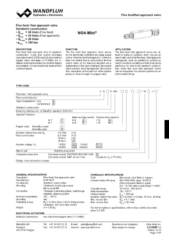
Fine feed/fast approach valve
CHaRaCTERISTICS Oil viscosity υ = 30 mm /s Fine feed- / fast approach valve
2
∆p = f (Q) Pressure drop-volume flow curve ∆p = f (Q) Pressure drop-volume flow curve Sandwich construction
2-way operation 3-way operation • Q max = 20 l/min (Fine feed) NG4-Mini ®
p [bar] p [bar] • Q max = 30 l/min (Fast approach)
25 K0351 25 K0352 • Q N max = 20 l/min
20 20 • p max = 350 bar
15 15
deSCrIPTION FUNCTION APPLICATION
10 10 Fine feed- / fast approach valve in sandwich The fine feed- / fast approach valve serves The fine feed- / fast approach valves are uti-
5 5 construction. 2-way flow control cartridges for the electrically controlled two-stage speed lised in hydraulic systems, which require an
(see data sheet 2.5-535) and 2/2-way solenoid control. Fine feed and fast approach. In the fine electrically controlled fine feed- / fast approach
0 0 poppet valve cartridges (1.11-2082) are in- feed, the volume flow is controlled by the flow changeover, such as positioning controls on
0 5 10 15 20 25 Q [l/min] 0 5 10 15 20 25 Q [l/min] stalled. 4 standard nominal volume flow ranges control valve, to the manually adjusted value machine tools or elevation controls of elevating
are available. The sandwich body made of steel independent on the load. In doing so, the poppet platforms, etc. Due to the sandwich construc-
Q = f (p) Leakage volume flow cruve
L is phosphatized. valve is closed. In the fast approach, the volume tion, these fine feed- / fast approach valves
Q [cm /min] flow, dependent of the load and of the system can be integrated into stacked systems as an
3
200 K0209 pressure, flows through the poppet valve. intermediate flange.
150
100 TyPe COde
50
V Q S A04 - - - / W #
0 Fine feed- / fast approach valve
0 50 100 150 200 250 300 350 p [bar] Flow control function
Type of adjustment Key S
DIMENSIONS Control knob D
Sandwich construction
Screw-in cartridgeS inStalled
20 Mounting interface acc. to Wandfluh standard, NG4-Mini
Ø 5.5 The following screw-in cartridges are used in the sandwich body:
Type list / Function Meter-out flow control Meter-in flow control in
Data sheet no.
Designation
Type
UZFSA06 UDFSA06 UZFPM22 2-way operation 2.5-630 in P P in A A in A BV
AV
B
in B
in B
T
in T
40 UDFPM22 3-way operation 2.5-630 Poppet valve Normally closed C
24 16 Normally open O
Nominal volume flow rate Q N 2,5 l/min 2.5
Flow control valve 6,3 l/min 6.3
10
4.2 120 14.2 16 l/min 16
32 20 l/min 20
21.5 19 Nominal voltage U N 12VDC G12 115VAC R115
24VDC G24 230VAC R230
T Slip-on coil Metal housing round
Connection execution Connector socket EN175301-803 / ISO 4400 D
A B
45 31 21 32.5 Connector socket AMP Junior-Timer J (only for U ≤ 75 VDC)
N
Design index (subject to change)
16
P
17.8
GeNerAL SPeCIFICATIONS HydrAULIC SPeCIFICATIONS
PaRTS lIST aCCESSORIES Description Fine feed- / fast approach valve Fluid Mineral oil, other fluid on request
NG4-Mini
Nominal size
®
Thread connection plates and rows of flange plates register 2.9 Contamination efficiency ISO 4406:1999, class 18/16/13
Position Article Description Construction Sandwich construction (Recommended filtration grade
A P T B A P T B Mounting 3 holes for socket cap screws ß 6...10 ≥75) refer to data sheet 1.0-50/2
10 160.2093 O-ring ID 9,25 x 1,78 M5 or studs M5 Viscosity range 12 mm /s...320 mm /s
2
2
20 238.2406 Locking screw VSTI G1/4"-ED Connection Threaded connection plates, multi-flange Fluid temperature -20...+70 °C
subplate, stacking system Peak pressure p max = 350 bar
Ambient temperature -20 ... +50 °C Nominal volume flow rates Q = 2,5 l/min, 6,3 l/min, 16 l/min, 20 l/min
N
Mounting any Min. volume flow Q = 0,1 l/min
min
Fastening torque M = 5,5 Nm (Qual. 8.8) for fixing screws Max. volume flow Q max = 30 l/min
D
cartridges: see valve data sheets
Technical explanation see data sheet 1.0-100 Weight m = 1,65 kg For further hydraulic specifications, refer to flow control valve data
sheet 2.5-535.
eLeCTrICAL ACTUATION
Solenoid construction: see data sheet poppet valve (1.11-2082)
Wandfluh AG Tel. +41 33 672 72 72 E-mail: sales@wandfluh.com Illustrations not obligatory Data sheet no. Wandfluh AG Tel. +41 33 672 72 72 E-mail: sales@wandfluh.com Illustrations not obligatory Data sheet no.
Postfach Fax +41 33 672 72 12 Internet: www.wandfluh.com Data subject to change 2.5-840E 2/2 Postfach Fax +41 33 672 72 12 Internet: www.wandfluh.com Data subject to change 2.5-920E 1/2
CH-3714 Frutigen Edition 03 43 CH-3714 Frutigen Edition 12 33
Page 1197